- Network
- A
Physical connection topology
In the process of its evolution from batch processing systems based on mainframes, computer networks have become increasingly complex, leading to a large number of options for connecting and arranging network components in space. This necessitated the need to choose the topology when connecting more than two computers to the system.
The essence of topology
Topology — is a graph whose vertices are end devices, and the edges act as communication lines.
A graph is one of the forms of representing a binary relation
The number of possible connections increases rapidly with the addition of new end devices. The number of connections will be understood as topologically different connections. Only graphs in which all vertices are combined into a single network are also considered.
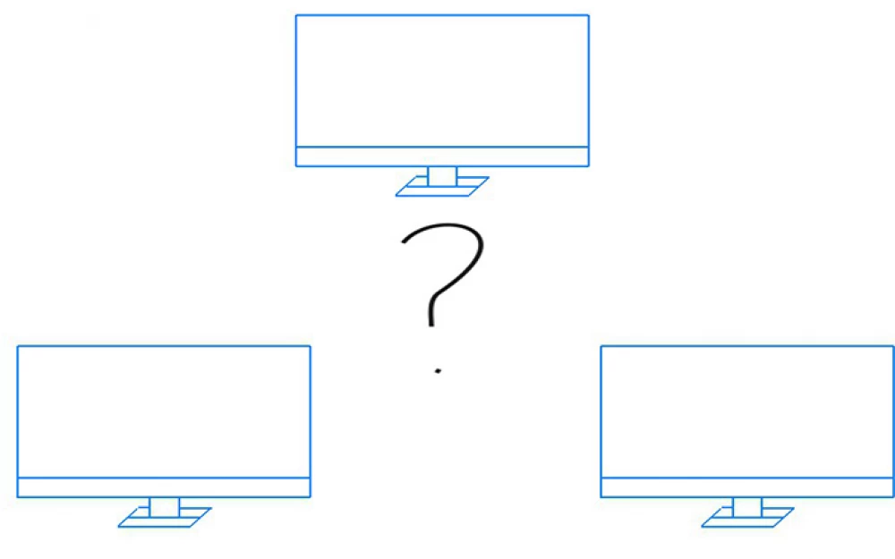
Three computers can be connected in only two ways (Figure 1).
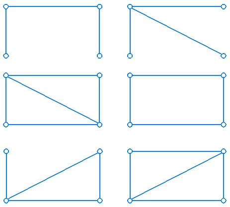
The number of combinations with four end devices is six (Figure 2).
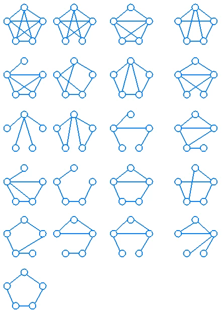
The number of combinations with five end devices is 21 (Figure 3).
End devices can be connected and combined as circumstances require, but in any case, transit nodes must have special means to transfer information from the sending node to the receiving node.
Before designing the network topology, it is necessary to assess the location and set the tasks to be solved. The solutions that will be used depend on this. For example, you can lay lines reserved for specific devices, create several paths between two nodes, which will allow load distribution in case of active use and increase reliability, etc. The economic issue occupies a special place in network construction, which sometimes leads to the choice of simpler solutions and the minimum total length of communication lines.
Every modern computer network must meet four basic characteristics:
Scalability
Provides quick and easy network expansion when needed.
Security
Restrict physical access to network devices (e.g., place them in a locked cabinet).
Prevent unauthorized access to devices (e.g., set passwords on computers, install a firewall, restrict the connection of new devices, use intrusion prevention systems).
Protect information transmitted over the network (e.g., use encryption, multi-factor authentication, password managers, access control lists).
Fault tolerance
Reduce the impact of failures by limiting the number of affected devices (e.g., create multiple paths from the end device).
Quality of Service
Using QoS. The topic of QoS is complex and extensive, so it will be briefly explained to clarify the reasons for its inclusion here. This technology creates traffic priorities. Marked QoS traffic is transmitted without queuing, while regular traffic goes into the buffer.
Physical and Logical Topology
Physical topology is the topology that shows how nodes are connected in a computer network.
Logical topology is the topology that shows how information will be transmitted in a computer network.
Usually, when talking about topology, they mean physical topology, which will be considered in this article, but one should not forget about logical topology, which is no less important when designing computer networks.
Fully Connected and Partially Connected Topology
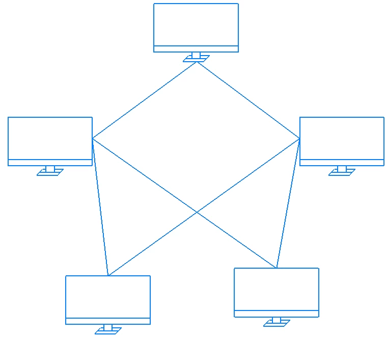
Fully connected topology is a topology in which each computer is connected to all others.
Partially connected topology is a topology in which each computer is not connected to all others and may require transit transmission for data exchange.
Fully connected topology is used very rarely because it has obvious disadvantages (Figure 4). Each computer must have a large number of communication ports, the number of which will increase according to the formula
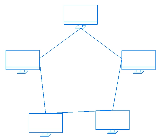
Ring topology speaks for itself by its name. In it, computers are connected sequentially, but the last computer connected in this way is connected to the first, forming a ring (Figure 6).
Ring topology is the most interesting because it involves link redundancy, as each network participant can send data both clockwise and counterclockwise. The cyclic nature allows for verification of information delivery to the recipient. Data leaving one computer can make a full circle, notifying it of their delivery. This property of the topology can be used to find the network segment that has failed. Two connections at a network participant increase fault tolerance, but if the node itself fails, the computer network will stop working. Network scalability is possible, but as the number of network nodes increases, its fault tolerance will decrease and data transmission time will increase. For example, when the number of computers in the network increases by two, the information will have to pass through another node. High-quality service is ensured by two paths for data transmission.
This topology is used in fiber-optic networks and by internet providers to organize the return transmission of data connecting central offices or head stations.
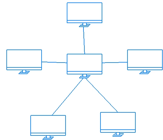
Star topology consists of computers directly connected to a common central device. This approach allows for the centralization of services, minimizing management costs and resource redundancy (Figure 7).
This approach to network creation ensures quick and easy scalability because to connect to a computer network, it is only necessary to run another line from the central device, which is a switch (in older networks, it could be a hub). The following solutions have been designed in such a network to increase its fault tolerance. Because all devices are connected to a central point, all failures such as cable breaks and equipment malfunctions are localized. Also, in such a network, it is easy to detect a faulty segment and restore it without creating network disruptions, which follows from the first solution to increase fault tolerance. For such a network, which includes a large number of nodes, the use of backup links is typical. The star topology reduces network congestion and decreases data transmission time due to the direct interaction of the device with the central element. The quality of service compared to the ring topology is lower because there is only one cable for data transmission, and the central element is a bottleneck for data transmission, as if all network participants simultaneously start transmitting their data, they will either be discarded or placed in a buffer, so when organizing such a topology, special attention should be paid to the buffer memory parameters of the network device to ensure it is sufficient to create a queue during overloads.
The star topology is used in high-speed local area networks due to its ease of maintenance, in creating multi-level networks, each level of which is a star, in networks that use twisted pair to connect devices.
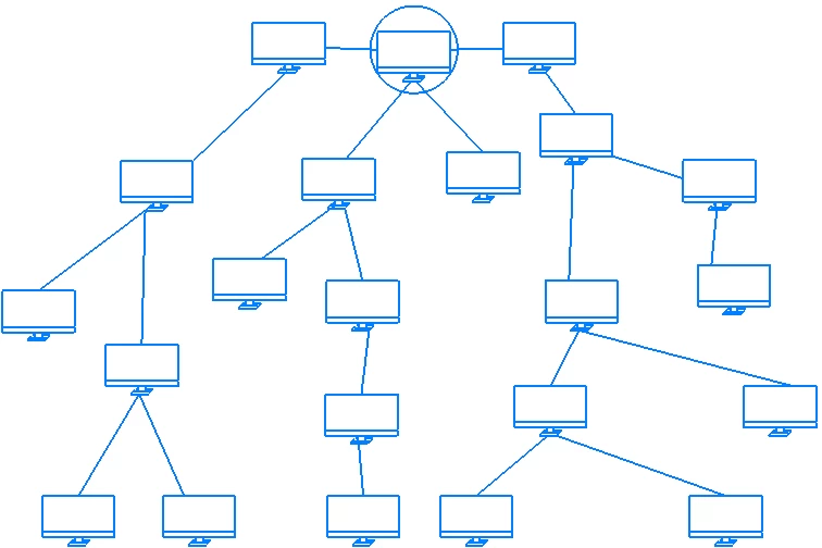
The hierarchical star topology (extended star) or tree —is the most common solution for creating computer networks today, both in local networks (LAN) and global networks (WAN).The topology is formed from a partially connected network, a star, by connecting new nodes that do not have direct contact with the central element (Figure 8).
This approach to network design has almost the same disadvantages and advantages as the star. In such networks, usually only network devices to which end users are connected have direct interaction with the central element.
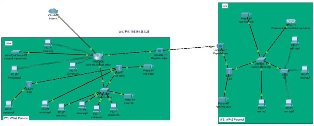
The hierarchical star is used in small, large, huge enterprises and offices. An example of using a hierarchical star for a factory consisting of two buildings, a workshop, and an office (Figure 9).
The common bus topology is a special case of the star topology (Figure 10).
Instead of a central element, a passive cable is used, to which end devices are connected. The wire becomes a common medium, that is, accessible to everyone, as well as the information that is distributed through it. Such a network has good scalability, since to connect a new computer, it is only necessary to connect it to the common cable, sometimes there is a need to extend it, which is easy to implement. The topology stands out among others for its cheapness, however, it has significant disadvantages: any breakage of the common cable paralyzes the network, which indicates low fault tolerance, low data transfer speed, due to the fact that only one computer can use the common medium for transmission at the same time (this ensures a high level of security, but also limits the number of network participants). To operate the network, it is necessary to install two terminals at the ends of the common cable. Another problem of the network is the high packet loss. Due to these disadvantages, such a topology has low quality of service.
The bus topology can be used as a segment of a large network, in which all computers are connected to a coaxial cable. Many wireless networks have a bus topology, with the radio medium acting as a common cable.
Mixed topology
Network segment — a logically or physically isolated part of the network.
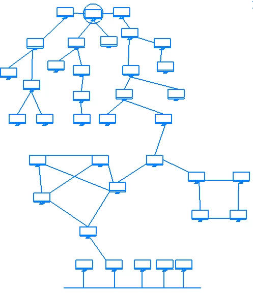
In small networks, star, bus, and ring topologies prevail, while large networks usually combine several topologies (Figure 11). For example, the hierarchical star topology may contain segments such as ring, star, bus, and others.
The mixed topology and its segments retain all the advantages and disadvantages of the topologies that are included in it.





Write comment