- DIY
- A
Resistor — it's simple. Not very
This note will be dedicated to such a simple thing as a variable wire resistor. But not so simple, from this family. At the moment when I thought that I already knew everything about variable and trimming resistors, amazing information surfaced for me...
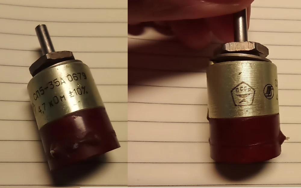
This note will be dedicated to such a simple thing as a variable wire resistor. But not such a simple resistor as many, but SP5-35A.
At the moment when I thought that I already knew everything about variable and trimmer resistors, amazing information surfaced for me.
But it was not that. My friend told me about a miracle resistor, where there are two variable resistances on one shaft at once, rough and precise, and a clever mechanism for their activation.
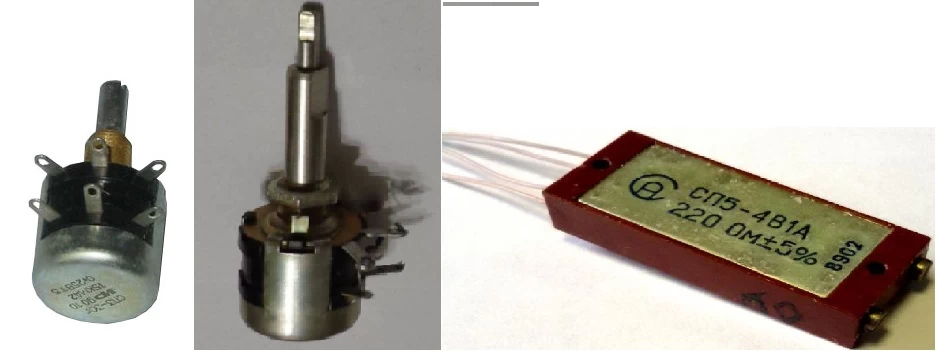
There was no reason not to believe this person, so I went to google, but by the time I approached my workplace, a link to the discussed device had already been carefully sent to me in the messenger. I really thought that I had seen and knew all the variable resistors, but here I was looking at the datasheet of a completely new device for me, but old for our society.
There are many different documentations on it, but the main points are as follows:
SP5-35A resistors - for surface mounting (1W)
SP5-35B resistors - for printed mounting (0.5W)
They are used to work in circuits of direct, alternating and pulsating currents with a voltage of up to 250 V.
The design of the resistors is based on a rough-precise scheme, has two resistive elements, while the movable systems are controlled from one shaft. When adjusting the resistance, the rotation of the movable system of the precise resistive element occurs first from stop to stop, and then the rotation of the movable system of the rough resistive element.
SP5-35 resistors are single-turn resistors with circular movement of the movable system.
Indeed, when rotating the engine, you can feel how it first moves easily, and after a certain point, the effort has to be increased. At the same time, it goes back easily again, and then the effort increases again. I really liked how it all feels.
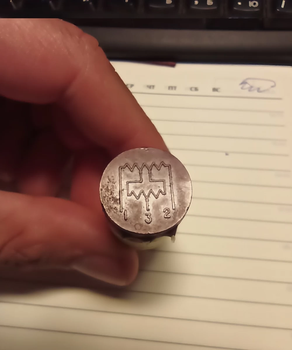
By the way, the diagram depicted from the end of the resistor quite succinctly conveys the essence of what is happening.
I connected a multimeter and looked at how it works. Well, I didn't see anything particularly unpredictable here.
Indeed, a small effort is responsible for a small, precise adjustment. After that, by resting and making a greater effort to turn, this smooth area moves across the entire range of adjustment up or down, depending on the direction of rotation.
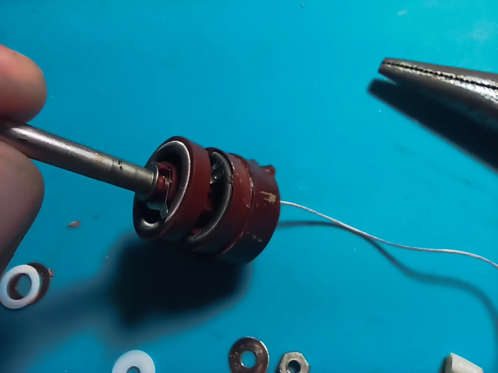
Using a soldering iron and ingenuity, I removed the back cover.
The first disassembly showed a rather primitive solution with signal transmission from the sliding contact during rotation. MGTF is a fairly flexible stranded wire that allows you to turn the resistor a lot and for a long time without fear that the contact will disappear. But I was a little disappointed. I really wanted to see something really unusual. Although, simplicity is sometimes genius.
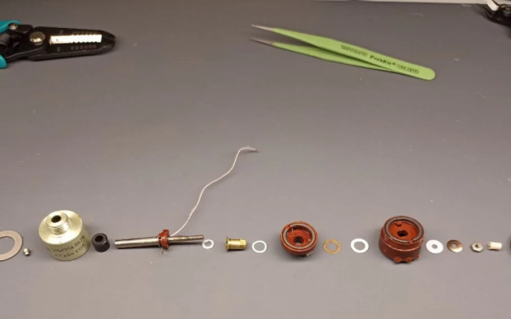
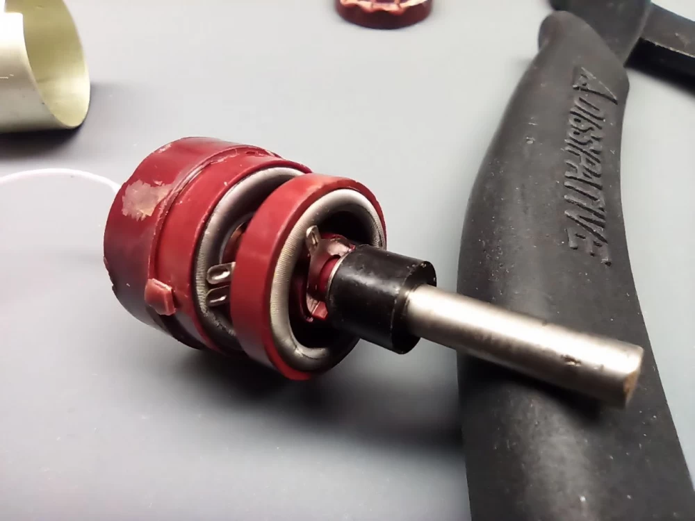
After unscrewing the nut, the aluminum cover is removed, and the entire resistor is disassembled. There are no more fasteners. And in this photo, you can see the essence of the device.
But when you turn it in your hands, it's much easier to understand. And it's harder to understand from the photo.
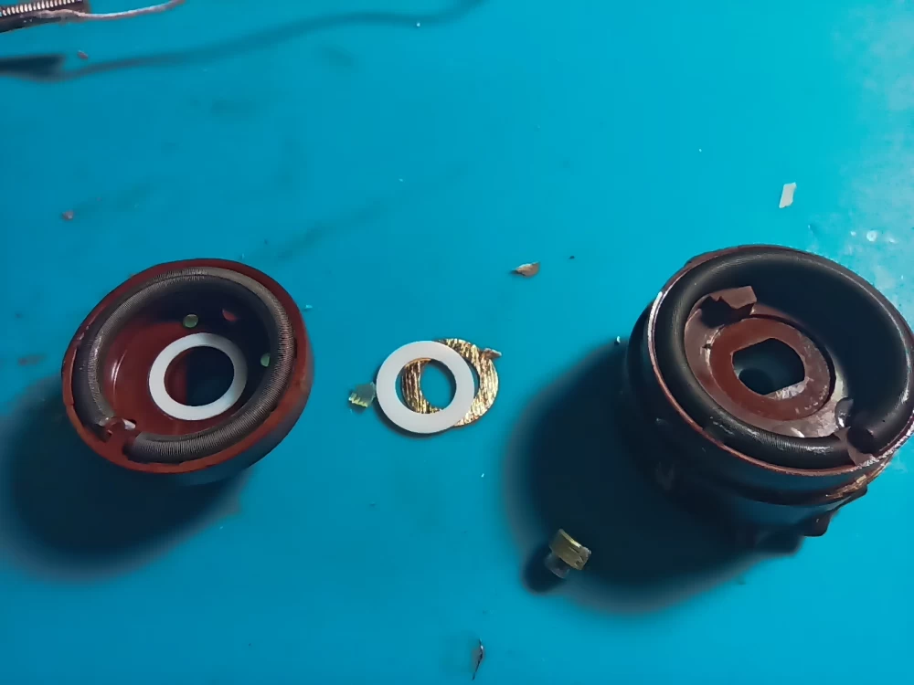
This is what two wire drums look like, on the left – precise adjustment, on the right – you understand:
The essence of the work is as follows:
Easy movement occurs along the low resistance coil. As soon as its runner – sliding contact, approaches the edge, the shaft catches on a special element and the movement along with the low resistance coil is transferred to the sliding contact along the larger coil.
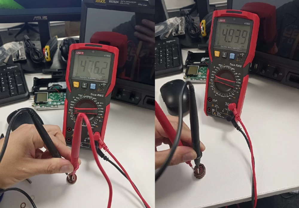
The smooth adjustment drum has a resistance of 476 ohms, and the total resistance of the resistor is 4.9 kOhms.
Am I explaining it confusingly? Of course, I'm not a designer. Let me show you in more detail:
Removing the coarse adjustment drum.
And removing the fine-tuning drum
The exploded view looks like this:
That's all. I hope someone else was also interested in looking at the design of such a resistor. I love elegant engineering solutions. And this solution has also proven to be quite reliable. Now I want to definitely use it in one of my devices.
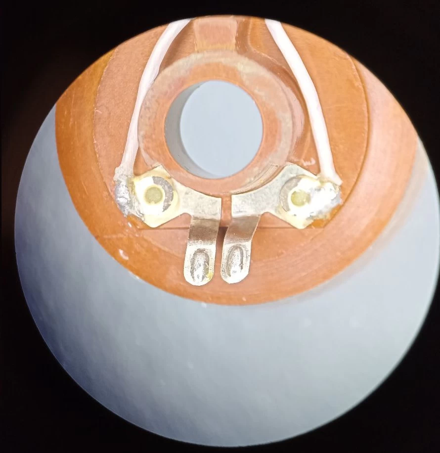
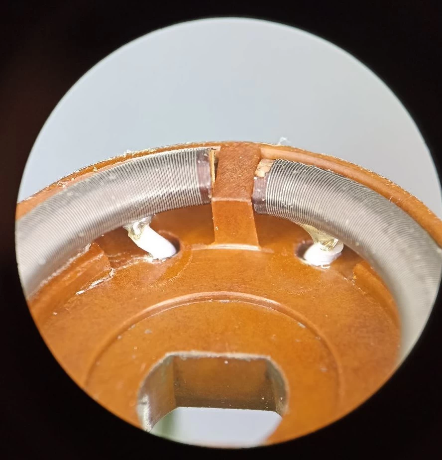
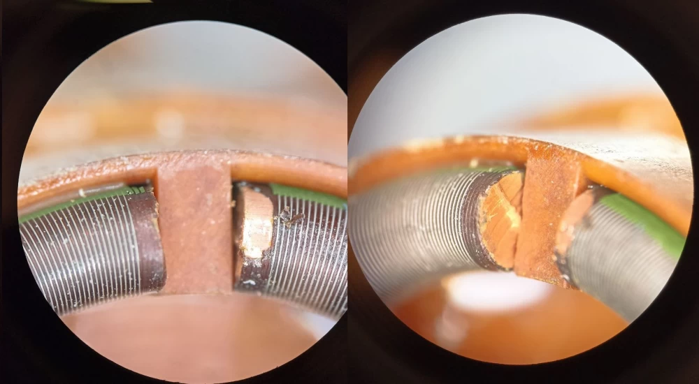
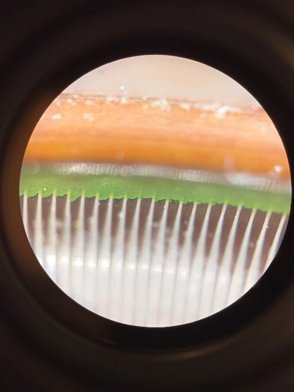
PS: For those who especially liked this device, I made some beautiful photos under a microscope, which can tell more about some features of SP5-35 in more detail.
If the contacts are more or less standard:
The wire winding has some features.
For example, the bobbin on which the coarse adjustment winding is implemented has a rise on one side.
The second interesting point is what the winding is made on.
The winding is made on a copper lacquered conductor. Ordinary copper lacquered wire.
The turns are fixed with glue (or varnish), green in color





Write comment