- Network
- A
How I created a device that can remotely emulate a mouse and keyboard on stm32
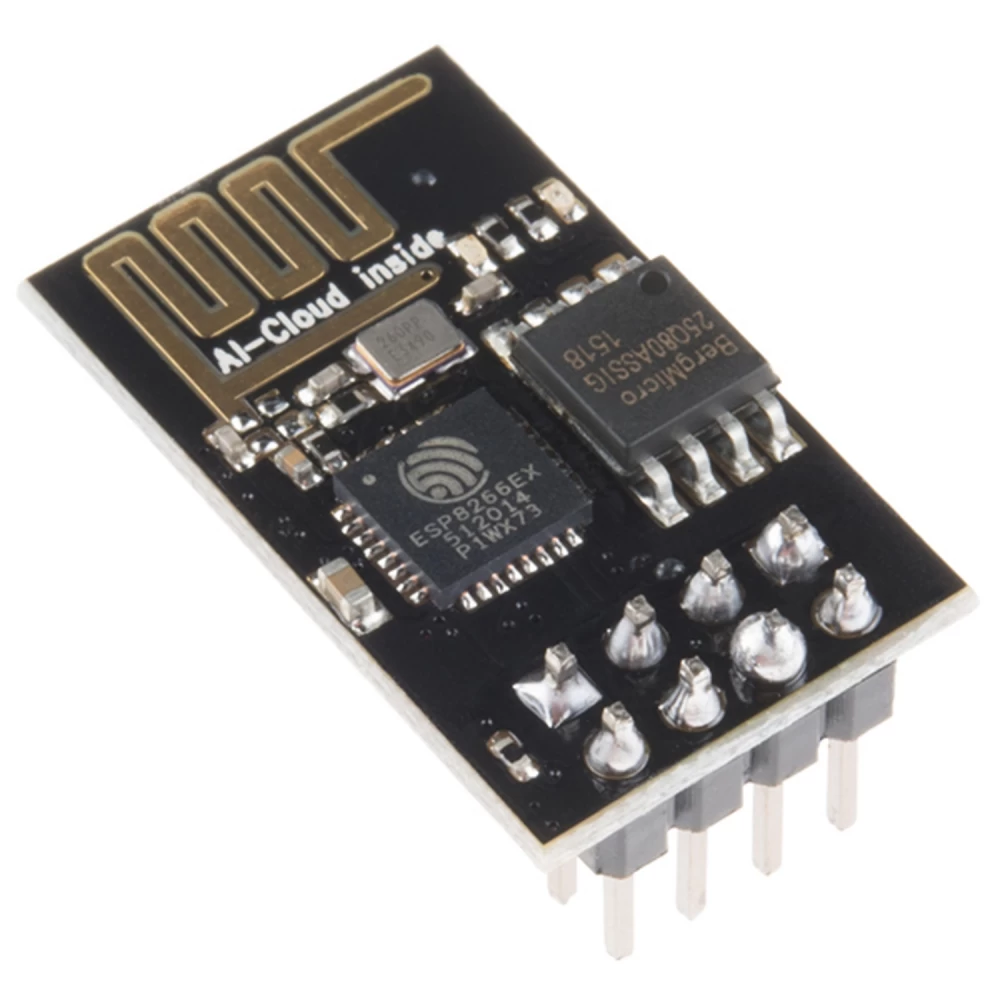
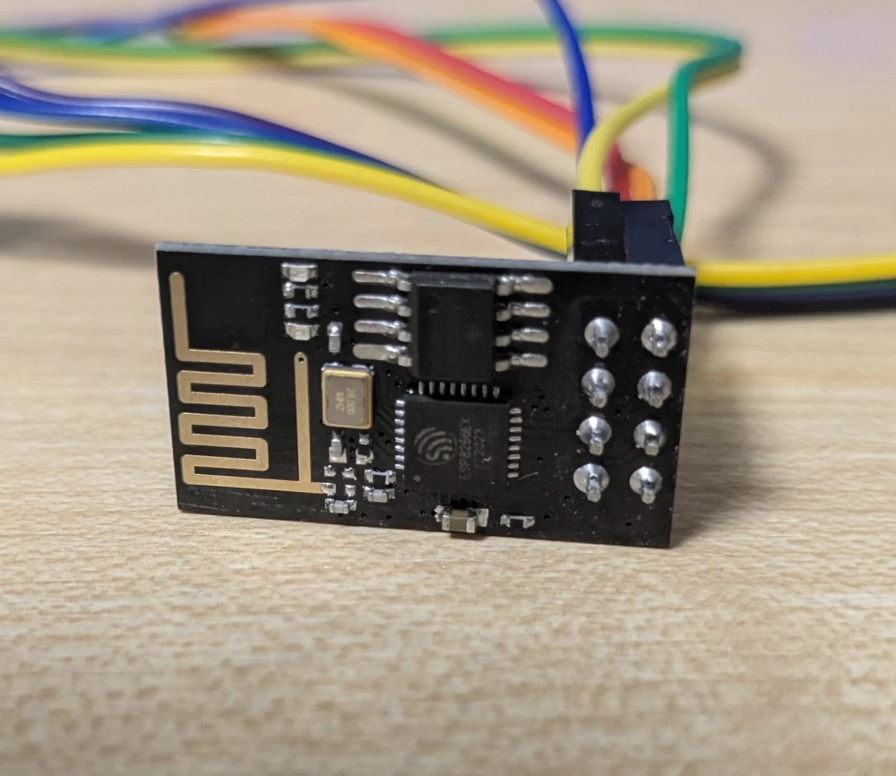
Hello everyone, I recently started studying the USB protocol on the STM32F103C8, namely HID devices. I am a person who does not really like theory, but loves to learn everything in practice, so I immediately started thinking about a future project. And I remembered that I recently ordered a wifi module - ESP8266.
1. How did the idea come about?
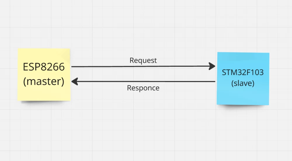
And then the idea came to me: why not combine the STM32f103c8 and ESP8266 into one device - UsbDeviceHacker (that's what I called it). My idea was to control the mouse and keyboard remotely via an API that would run on a web server hosted on the ESP. Accordingly, the ESP would act as the master device, and the STM32 as the slave.
Many may ask: why not make everything much simpler and use bluetooth instead of wifi, but using wifi will be much more interesting because our web server will be deployed in the local network, and accordingly, any device in it will be able to control the device simply by sending an HTTP request to the desired ip.
2. Project model
Before starting the implementation, it is necessary to describe the working model of the device, I will start with the ESP8266. The wifi module connects to an external access point and creates a web server in its local network. Its API has 8 endpoints (POST), each of which is responsible for its own functionality.
The /mouse and /keyboard endpoints allow direct access to the mouse and keyboard, i.e. to use them according to their official documentation. The /animation endpoint already uses ready-made functionality that makes it easier to work with the device.
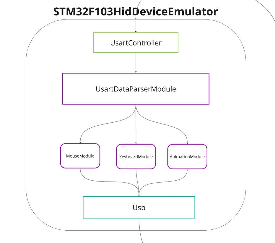
After sending a correct request, the ESP8266 forms a packet and sends it via UART directly to the STM32F103C8. The Blue pill receives the data and checks it for correctness, if everything is fine, it sends a report to the USB.
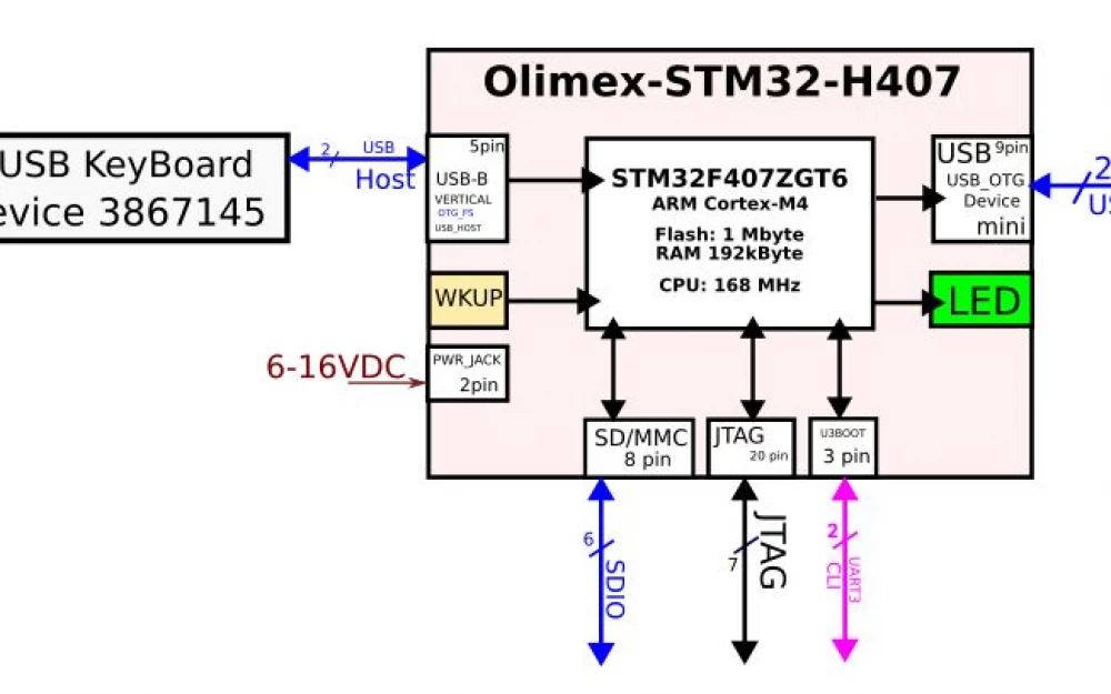
The full project architecture can be viewed in miro.
3. Implementation of ESP8266
I wrote the firmware for ESP8266 using PlathormIO,in Visual Studio Code. I will not dwell too much on explaining the code, but will just tell everything in general terms, otherwise the article may be too long. In any case, you can view everything yourself, the repository is public, here is the link.
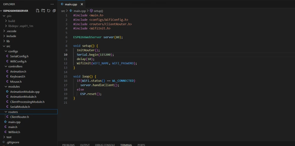
In general, the project structure looks like this:
I designed the working folder as follows: it consists of 4 folders: configs, controllers, modules, routes, and files main.h and main.cpp. The function InitRouter() creates endpoints using the ESP8266WebServer.h library and redirects them to controllers. For controllers, instead of classes, I decided to use namespaces, simply because it is clearer and more convenient.
 void InitRouter(){
     server.on("/mouse/set", Mouse::set);
     server.on("/mouse/remove", Mouse::remove);
     server.on("/mouse/click", Mouse::click);
     server.on("/keyboard/set", Keyboard::set);
     server.on("/keyboard/remove", Keyboard::remove);
     server.on("/keyboard/click", Keyboard::click);
     server.on("/animation/set", Animation::set);
     server.on("/animation/remove", Animation::remove);
 }
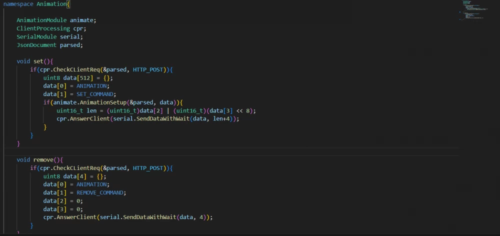
And then all the main actions take place in the controllers. Here is an example of the Animation.h controller:
To parse JSON, I use the ArduinoJson.h library. It is very convenient and greatly facilitates the work, with it you can: easily parse, filter data and create JSON objects yourself.
The package for STM32 is formed in the data array and sent using the SendDataWithWait(uin8_t *data, uint8_t len) function of the serial class. To check the correctness of the data, a checksum crc8 is added to the last byte of the package.
string SendDataWithWait(uint8_t *data, uint16_t len){
    uint8_t data_out[len+2] = {HEADER,};
    for(int i = 0; i
ESP8266 waits for a response from STM32 in the AwaitResponse() function, after which it sends the response to the client. All client-side work is implemented in the ClientProcessingModule.h file.
One of the problems when creating a web server is its dynamic IP. When connected to a router or modem, the device is assigned an IP that changes over time. Because of this, you have to constantly connect the ESP8266 to the serial port and check it manually. There are two solutions to this problem: the first, if the device connects to the router, you can set a static IP; the second, send the dynamic IP to the web server with a static IP.
At the moment, I am not using either solution, simply because I don't need it yet.
4. Connection
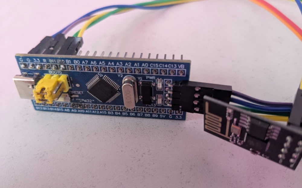
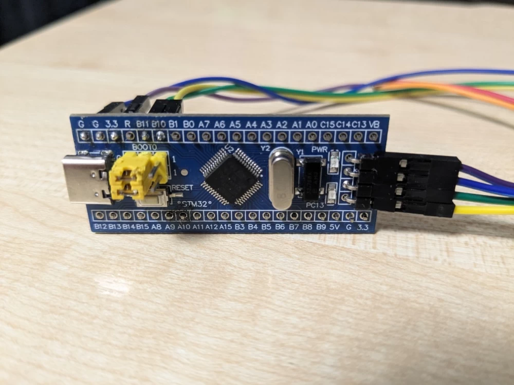
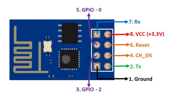
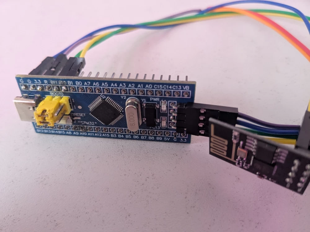
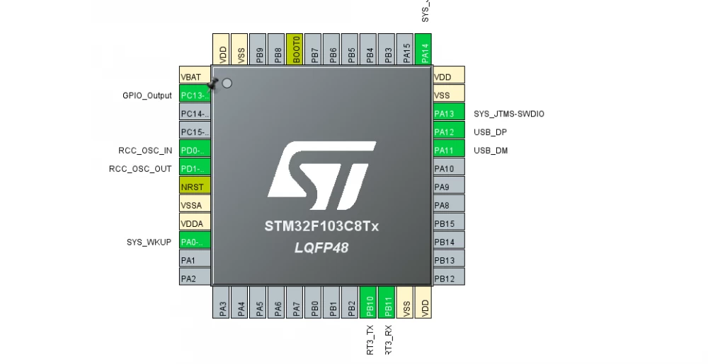
To start working with STM32, you need to figure out how to connect the ESP8266 to it. Since the blue pill will be connected via USB, the ESP will be powered by it. The VCC and CH_EN pins are connected to the 3.3V pin on the STM32, GND to GND, RX to B10, TX to B11, and that's it.
On the STM32, pins B10 and B11 are TX and RX of USART3, respectively.
5. Implementation of STM32f103C8
I wrote the firmware for STM in CubeIDE. The code for it is quite simple, it is written entirely in C. The protocols connected are UASRT3 (HAL), which receives requests from the ESP, and, in fact, USB, which is configured as a HID-device. An LED is also added to PC13.
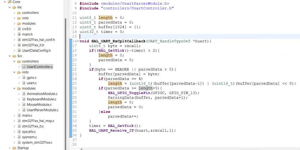
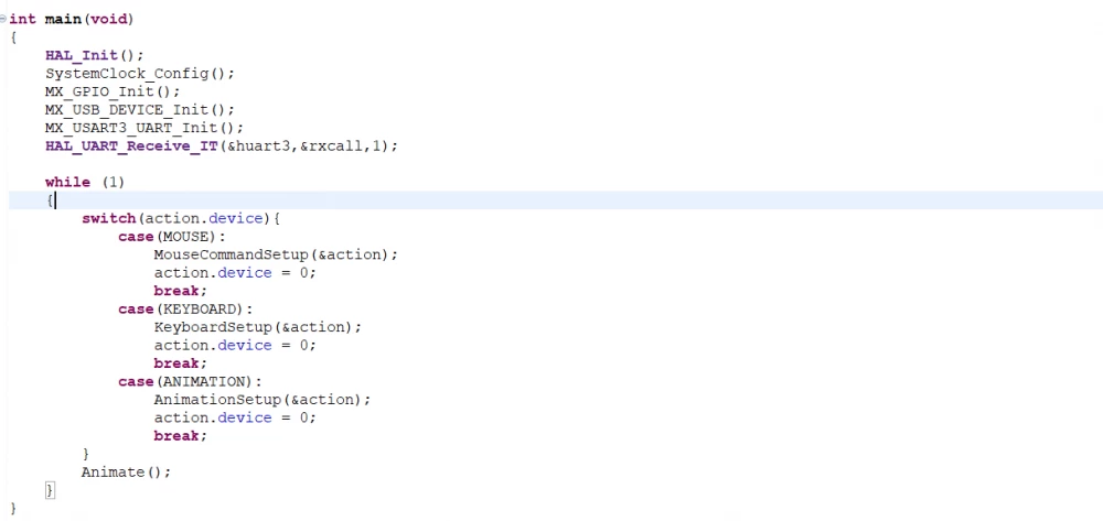
The project structure consists of 3 folders: inits, modules, controllers. Data from USART3 is received in the UsartController.c file, in HAL_UART_RxCpltCallback, where they are received one by one and collected in the buffer array, after which the ParsingData function is called, which checks for correctness using crc8, and fills the Action structure with verified data.
After receiving the packet, the necessary case in main.c is triggered, where the data processing function is started, where the main work takes place. Then, depending on the device and command, the data forms a report, which is sent via USB.
To send reports for both the mouse and keyboard simultaneously, you need to write the following instructions in the HID_MOUSE_ReportDesc function, which is located in the usbd_hid.c file:
0x05, 0x01, /* Usage Page (Generic Desktop) */
0x09, 0x02, /* Usage (Mouse) */
0xA1, 0x01, /* Collection (Application) */
0x09, 0x01, /* Usage (Pointer) */
0xA1, 0x00, /* Collection (Physical) */
0x85, 0x01, /* Report ID */
0x05, 0x09, /* Usage Page (Buttons) */
0x19, 0x01, /* Usage Minimum (01) */
0x29, 0x03, /* Usage Maximum (03) */
0x15, 0x00, /* Logical Minimum (0) */
0x25, 0x01, /* Logical Maximum (0) */
0x95, 0x03, /* Report Count (3) */
0x75, 0x01, /* Report Size (1) */
0x81, 0x02, /* Input (Data, Variable, Absolute) */
0x95, 0x01, /* Report Count (1) */
0x75, 0x05, /* Report Size (5) */
0x81, 0x01, /* Input (Constant) ;5 bit padding */
0x05, 0x01, /* Usage Page (Generic Desktop) */
0x09, 0x30, /* Usage (X) */
0x09, 0x31, /* Usage (Y) */
0x15, 0x81, /* Logical Minimum (-127) */
0x25, 0x7F, /* Logical Maximum (127) */
0x75, 0x08, /* Report Size (8) */
0x95, 0x02, /* Report Count (2) */
0x81, 0x06, /* Input (Data, Variable, Relative) */
0xC0, 0xC0,/* End Collection,End Collection */
//
0x09, 0x06, /* Usage (Keyboard) */
0xA1, 0x01, /* Collection (Application) */
0x85, 0x02, /* Report ID */
0x05, 0x07, /* Usage (Key codes) */
0x19, 0xE0, /* Usage Minimum (224) */
0x29, 0xE7, /* Usage Maximum (231) */
0x15, 0x00, /* Logical Minimum (0) */
0x25, 0x01, /* Logical Maximum (1) */
0x75, 0x01, /* Report Size (1) */
0x95, 0x08, /* Report Count (8) */
0x81, 0x02, /* Input (Data, Variable, Absolute) */
0x95, 0x01, /* Report Count (1) */
0x75, 0x08, /* Report Size (8) */
0x81, 0x01, /* Input (Constant) ;5 bit padding */
0x95, 0x05, /* Report Count (5) */
0x75, 0x01, /* Report Size (1) */
0x05, 0x08, /* Usage Page (Page# for LEDs) */
0x19, 0x01, /* Usage Minimum (01) */
0x29, 0x05, /* Usage Maximum (05) */
0x91, 0x02, /* Output (Data, Variable, Absolute) */
0x95, 0x01, /* Report Count (1) */
0x75, 0x03, /* Report Size (3) */
0x91, 0x01, /* Output (Constant) */
0x95, 0x06, /* Report Count (1) */
0x75, 0x08, /* Report Size (3) */
0x15, 0x00, /* Logical Minimum (0) */
0x25, 0x65, /* Logical Maximum (101) */
0x05, 0x07, /* Usage (Key codes) */
0x19, 0x00, /* Usage Minimum (00) */
0x29, 0x65, /* Usage Maximum (101) */
0x81, 0x00, /* Input (Data, Array) */
0xC0 /* End Collection,End Collection */
Where the report id of the mouse will be 0x01, and the keyboard will be 0x02, i.e. the data for the mouse, for example, should be sent in the following format:
 uint8_t data_out[5] = {0x01, 0, 0, 0, 0}; // first byte - report id
 USBD_HID_SendReport(&hUsbDeviceFS, data_out, 5);
Special attention should be paid to animations, because they add ready-made functionality to the device. Currently, 3 animations are available:
1) smooth mouse movement - the mouse moves smoothly along the x or y axis, you can set the direction and speed of movement from 1 to 10 inclusive;
2) automatic text typing (only Latin characters, numbers and spaces work) - sequential text typing, you can set the text and repetitions of its writing, for example, type "Hello World" every 10 seconds.
3) mouse movement in a circle -just the mouse moves in a circle, you can set the speed from 1 to 10 inclusive and the radius of movement.
Also, you can set mouse button press statuses for animations 1 and 3, for example, let the mouse move in a circle with the right mouse button (RMB) or left mouse button (LMB) pressed, or all at once. There are three statuses available: LMB, RMB, and the mouse wheel button.
API documentation here.
6. Tests
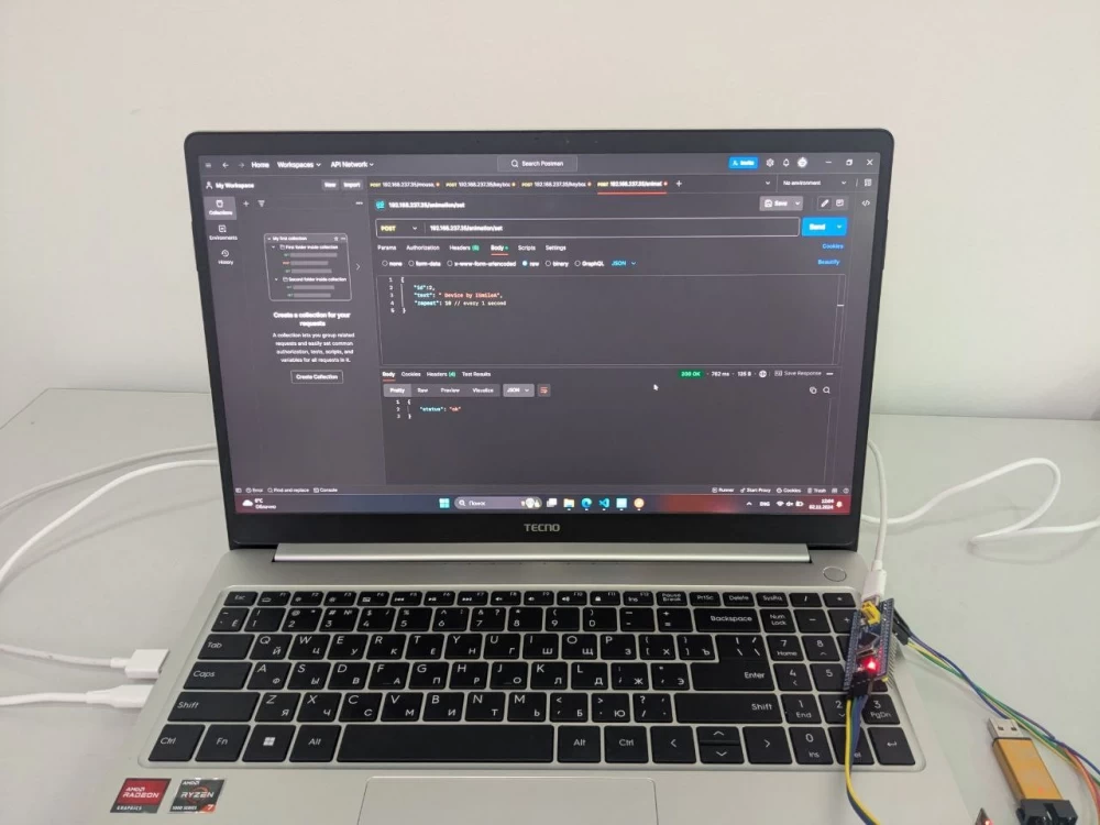
Now we have reached the most interesting part, namely the tests. Connect the device to the PC (laptop) and wait for the ESP to connect to the modem. I shared a hotspot from my phone and also connected to it from my laptop to send requests from it. As a result, I will start from the laptop and stop from the phone by sending a request to the /remove endpoint.
Here is the link to the video with the tests:
UsbDeviceHackerTestrutube.ruThat's all, as I think, it turned out to be a very interesting project, which definitely deserved the effort and time spent on it. I leave a link to the public git repository, where you can find all the details. Subscribe to my telegram channel, where I publish information about my projects and life in general. I wish everyone good luck, I hope to see you again.




Write comment