- Network
- A
Simply About the Complex. All You Wanted to Know About SFP Modules. Part 5. SFP Modules with WDM/CWDM/DWDM Multiplexing Technologies
Greetings, colleagues! It’s @ProstoKirReal again. In previous articles, I discussed with you the operation and development history of SFP modules, their DAC and AOC alternatives, as well as optical cables and passive components:
In this article, I would like to discuss SFP modules with multiplexing technologies with you.
❯ Why is this article needed?
This article is needed for us to understand basic concepts and cover:
what WDM is;
what CWDM is;
what DWDM is;
how to choose a DWDM/CWDM SFP module;
how multiplexers and demultiplexers work;
what to look for when choosing a WDM system.
❯ Why is multiplexing technology needed in general?
The classic connection scheme for SFP modules looks like this:
SFP module TX → one fiber of duplex patch cord → SFP module RX
SFP module RX ← one fiber of duplex patch cord ← SFP module TX
Each fiber transmits its own light pulse at a single wavelength, so the amount of transmitted data is limited.
For standard networks this is not a problem, you can add more modules and increase bandwidth. But what if you have an 8-fiber cable buried in the ground, and you need to organize 16 independent channels between campuses/data centers or connect dozens of base stations? Laying new fiber optics is expensive and time-consuming.
What to do then?
Multiplexing technologies or WDM come to the rescue.
❯ What is WDM and why is it needed?
WDM (Wavelength Division Multiplexing) – is a technology that allows transmitting multiple independent signals over a single optical fiber, each on its own wavelength.
A simple analogy. Imagine a regular single-lane dirt road. Cars (data) can only move along it one after another, which limits data transfer speed. Now we will replace the dirt road with a multi-lane highway. Now traffic can move in parallel, thereby increasing data transfer speed.
WDM is precisely what allows turning an ordinary single-lane dirt road into a multi-lane motorway.

Why is this needed?
The top priority task – is saving optical fibers. In a single optical fiber, instead of one signal, you can transmit dozens of separate independent channels, using a unique light wavelength for each;
Increasing bandwidth without laying new optical fibers. This is especially critical for trunk lines, where every kilometer of new optical cable costs a fortune.
❯ How does WDM work?
There are several ways to organize a duplex communication channel over a single (simplex) optical fiber.
They are all based on the second law of optics, which states that light rays propagate independently of each other. That is, rays do not affect one another, and propagate as if other rays do not exist.
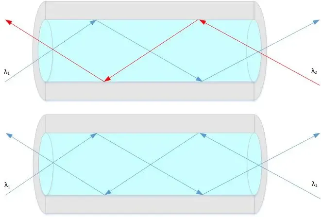
Bidirectional (BiDi)
BiDi technology – is a specific case of WDM, in which two wavelengths are used to organize a duplex channel over a single fiber.
The essence of BiDi is simple – organizing high-speed duplex channels with data transmission at different wavelengths, for example 1270 and 1310 nm
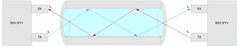
A WDM filter (multiplexer/demultiplexer) is built into the module, which physically separates two wavelengths. The laser emits at one wavelength (e.g., 1310 nm), and the photodiode receives only at another (1550 nm). Both signals are transmitted over the same fiber simultaneously but do not interfere with each other because the optical filters on reception and transmission are tuned to their "own" waves.
Key point. When using a "one-eyed" WDM module, a paired module with mirrored wavelengths must be installed at the opposite end, for example, TX 1550 nm / RX 1310 nm.
To make it easier to find a paired module, manufacturers often swap the numbers indicating the wavelengths in the article numbers, for example: XX-YY35ZZZZ and XX-YY53ZZZZ.
Or such modules come in a set immediately
For example, this one.
❯ Transmission over WDM optical fiber
Actually, what does it look like in reality?
With regular SFP-WDM modules, everything is simple. These modules are usually "one-eyed" with SC or LC connectors (For Bidi at speeds from 10GE and above, only LC connectors are used). They are connected by regular patch cords between each other. In between, there may be optical cross-connects that switch a regular line to a trunk line.
To multiply the bandwidth of the channels, CWDM or DWDM multiplexing is used.
I will talk about these technologies a little below, but now let's look at how it all looks.
Many SFP modules with different wavelengths are connected to a single multiplexer, which combines all channels from these modules and directs them into an optical fiber. On the other side is a demultiplexer that separates the channels and directs the flows to specific modules with specific wavelengths.
For DWDM, optical amplifiers are used to increase the length of the trunk channel.
Interestingly, the transmitter (TX) operates at a strictly specified wavelength, while the receiver (RX) is usually broadband, which allows receiving and detecting signals at various wavelengths.
Sample circuit diagrams are shown in the images below.
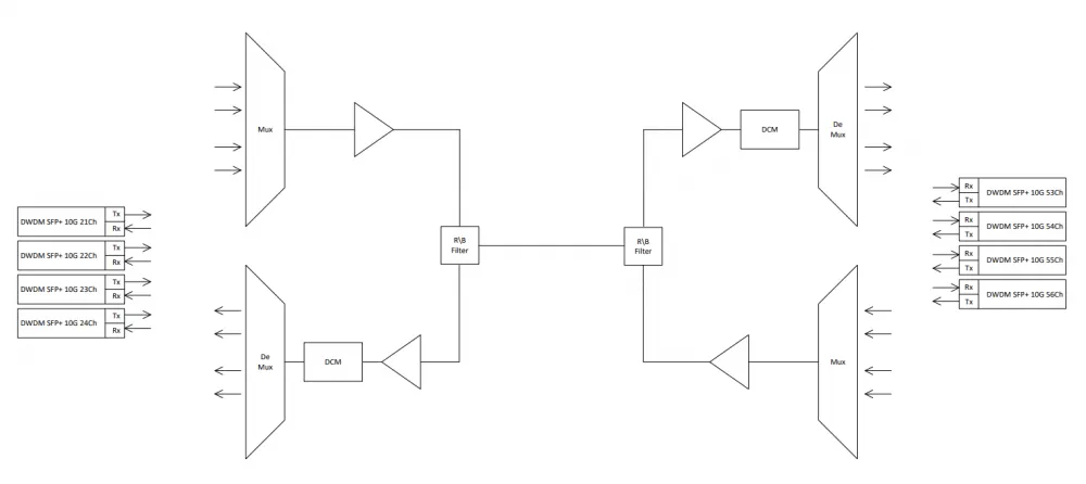
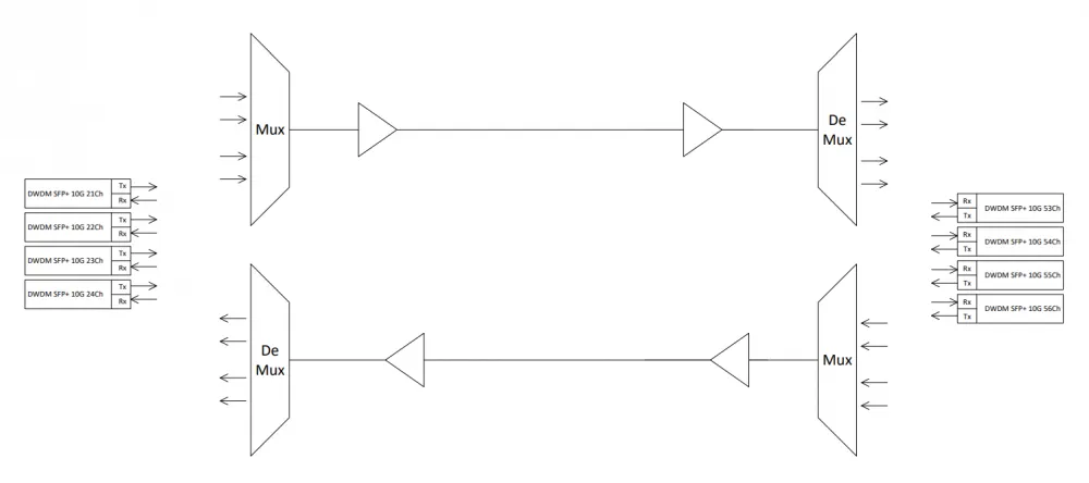
Now let's discuss each component individually in detail.
❯ What is CWDM?
CWDM (Coarse Wavelength Division Multiplexing) is a technology for coarse spectral multiplexing. The term "coarse" is related to the relatively wide channel spacing used, which is 20 nm.
Why is it called "coarse"? Historically, CWDM uses a wavelength range that is incompatible with EDFA optical amplifiers. This limited the technology's application in ultra-long-haul trunk lines, but it turned out to be ideal for use cases with distances of up to 60–80 km.
CWDM technology is based on the propagation characteristics of light at different wavelengths. Light at different wavelengths travels at different speeds in a medium with a constant refractive index, and does not interact with each other when the wavelengths are sufficiently spaced apart.
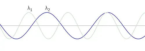
In 2002, the International Telecommunication Union (ITU) standardized the CWDM wavelength grid in document G.694.2. The CWDM wavelength grid uses wavelengths from 1270 to 1610 nm, with a channel spacing of 20 nm.
This grid was revised in 2003, shifting it by 1 nm to the 1271–1611 nm range, however most CWDM equipment manufacturers and CWDM system users use values from the older 1270–1610 nm grid for wavelength designations.
In practice, the 1 nm difference is not critical, but it is worth knowing this to avoid confusion in specifications.
CWDM characteristics:
Operating range: approximately 1270-1610 nm;
Channel spacing – 20 nm;
Maximum number of channels – 18. In practice, 8 or 16 are more commonly used, as part of the range may fall into "windows" of increased attenuation.
Naturally, 18 channels are simplex channels, which allow organizing up to 9 duplex communication channels. Each of these 9 channels can be organized according to any of the existing data transmission protocols, whether it be Fibre Channel, STM, GE, Ethernet, or an analog cable television signal.
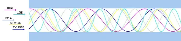
Advantages of CWDM:
Simple and inexpensive components (lasers, MUX/DEMUX);
Fewer requirements for wavelength accuracy – simpler to configure and cheaper to operate;
Excellent for "short" networks (urban, corporate, operator networks up to 80 km).
Disadvantages of CWDM:
Limited number of channels;
Not suitable for ultra-long highways.
❯ What are "windows" with increased attenuation?
Above, I mentioned "windows" with increased attenuation. Let's briefly examine what this is.
A "window" with increased attenuation, or otherwise known as a "water peak" – is a region with high losses around 1300 nm in the fiber, affecting CWDM channels from 1370 to 1430 nm. In this region, losses can reach up to 1.2 dB/km, whereas in the 1550 region, it's 0.25 dB/km.
However, these channels are still used, although it's necessary to pre-calculate the attenuation they introduce.
But there are also specialized cables with zero water peak, such as OWP (Zero Water Peak Fiber), allowing the expansion of the operating wavelength range.
CWDM solves the problem of "increasing fiber capacity N-fold" in the most direct and cost-effective way. When hundreds of kilometers and dozens of channels are required, DWDM comes into play.
❯ What is DWDM?
DWDM (Dense Wavelength Division Multiplexing) is dense wavelength division multiplexing. DWDM systems are based on the ability of optical fiber to simultaneously transmit light of different wavelengths without mutual interference. Each wavelength represents a separate optical channel.
Backbone networks all over the world are built on this technology.
What DWDM is:
this is "dense" multiplexing, where in different implementations, wavelength grids with spacing between adjacent carriers of 12.5, 25, 50, 100, and 200 GHz are used;
unlike CWDM, DWDM works in conjunction with EDFA optical amplifiers, which makes it possible to build lines spanning thousands of kilometers;
the number of channels can reach up to 96, but in practice no more than 40 are used (standard C-band and L-band grids).
When operating over long distances and with high channel density, compensation for optical signal attenuation is required. EDFA amplifiers are used for this purpose, which amplify signals in the C-band grid.
Why is DWDM relevant today?
traffic growth, cloud services, video, AI – all of this requires enormous bandwidth. DWDM makes it possible to increase capacity without laying new fiber, simply by adding new wavelengths;
modern equipment has become more affordable. Compact OTN platforms, auto-tuning transponders, and support for modern standards have appeared. All of this lowers the entry threshold, bringing DWDM closer to operator networks and large data centers;
DWDM scales easily along with the network. New channels can be added without a global overhaul of the backbone;
with the emergence of ROADM (Reconfigurable Optical Add-Drop Multiplexer), managing such a network becomes similar to software-defined (SDN) infrastructure.
What should you pay attention to when designing a DWDM network?
Is there support for amplifiers and stabilized lasers? Without these, long routes will not be stable;
What speeds are required? 100G, 400G and above? It is important that the equipment supports modern interfaces and protocols;
Is expansion planned? You should always have spare channel capacity, as there is always a possibility of expansion;
Network management – it is desirable to have support for modern monitoring systems, virtual channel creation, redundancy, and protection.
Comparison of CWDM and DWDM. Which one to choose?
At first glance, both systems do the same thing, allowing multiple independent channels to be transmitted over a single fiber. But the main difference is channel placement density, which leads to differences in equipment complexity and cost.
Let's briefly review the key differences in the table.
CWDM | DWDM | |
Number of channels | Up to 18 | up to 96 (standard C-band and L-band grid) |
Cost | Significantly cheaper due to lower-cost uncooled lasers, lower wavelength accuracy requirements, and the use of passive MUX/DEMUX | Significantly more expensive due to cooled lasers, transponders, optical amplifiers, and channel monitoring systems |
Loss tolerance | Higher | Lower |
Transmission distance | Up to 100 km (without amplification) | More than 100 km, thanks to optical amplifiers (EDFA or Raman) |
❯ Which one to choose?
When is CWDM the best choice?
Despite limitations in transmission distance and number of channels, CWDM remains one of the most popular multiplexing technologies. It is ideal for situations where you need to increase fiber capacity relatively inexpensively.
CWDM is used in the following scenarios:
connecting multiple campus or enterprise buildings;
connecting small data centers;
aggregating GPON or Ethernet traffic;
connecting district telecom nodes;
operator city networks.
The main advantage is the low entry barrier. You can start a network with 2-4 channels, gradually adding new ones as needed.
In addition, CWDM systems operate fully passively, with no active equipment between nodes. This reduces power consumption and simplifies maintenance.
When is DWDM the best choice?
Many people think DWDM is only used by large telecom operators, but that's not entirely true. There are many clients I have worked with who use DWDM when they need to set up communication lines between different branches. The banking sector, which is obsessed with protecting its own networks, is especially fond of doing this.
DWDM is also used in the following scenarios:
trunk lines between cities;
connections between large data centers;
operator backbone networks (core internet networks that aggregate traffic);
submarine communication lines;
high-load segments of operator networks.
The main advantage is scalability. Even if a small number of channels are used initially, DWDM allows you to add more and more wavelengths, leaving reserve capacity for the future.
Hybrid Networks
Interestingly, these technologies are used together in real-world networks.
For example, an operator can build a trunk line using DWDM, and use CWDM in urban segments to aggregate traffic.
This architecture allows:
reduce infrastructure costs;
maintain high trunk capacity;
flexibly scale the network.
In practice, CWDM acts as the aggregation layer, while DWDM is the network's trunk layer.
❯ How to choose a DWDM/CWDM SFP module?
Well, now for the reason we're all here. How to actually choose these very modules.
At first glance, it's simple. You take a module of the required wavelength and connect it to equipment. But in practice, there are several important parameters you need to check in advance.
Wavelength
This is the main parameter of a WDM module.
For CWDM, the wavelength is selected from the standard frequency grid.
Each channel in the system must use its own unique wavelength, otherwise signals will conflict.
Important! Each module connects to the corresponding multiplexer channel. If the wavelength does not match, the signal simply will not pass through the filter.
For DWDM, the situation is a bit more complex. Instead of wavelength in nanometers, it uses ITU grid channel number.
Therefore, when selecting a DWDM module, you need to make sure that the channel number matches the configuration of the MUX/DEMUX or transponder.
Data transfer rate
The most important parameter is the supported interface speed.
WDM modules are produced for different speeds:
1Ge (SFP);
10Ge (SFP+);
25Ge (SFP28);
40Ge (QSFP+);
100Ge (QSFP28).
It is important to understand that the multiplexer does not limit the channel speed. It only combines wavelengths.
Therefore, almost any protocols can be transmitted over CWDM or DWDM:
Ethernet;
Fibre Channel;
OTN;
SDH / SONET;
GPON.
The most important thing is that the module and network equipment support the required interface.
Transmission range
Each SFP module has a maximum transmission range parameter.
Typical values:
10 km;
20 km;
40 km;
80 km;
120 km and more.
This parameter depends on:
laser power;
photodetector sensitivity;
type of optical fiber;
presence of amplifiers.
Fiber type
All modern WDM systems operate on single-mode (SMF) fiber. The following standards are mainly used:
G.652;
G.655;
G.657.
For DWDM backbone lines, ordinary G652.D fiber with a pronounced water peak is often used, so additional losses on certain CWDM channels must be taken into account.
Zero-dispersion fiber is very expensive and is almost never used in practice.
It is best remembered when you provide examples.
Example 1. 2x10G line between two buildings 10 km apart
It is necessary to connect two switches between the company's buildings, and only one optical fiber is available. In this case, a CWDM solution can be used.
For example:
Each CWDM transceiver has a transmitter that operates at a specific wavelength, and a receiver that can detect any signal in the wavelength spectrum from 1270 to 1610 nm.
To solve this task, you can use the following equipment selection:
Side A
SFP+ transceiver with wavelength 1270
SFP+ transceiver with wavelength 1290
CWDM multiplexer
Side B
SFP+ transceiver with wavelength 1310
SFP+ transceiver with wavelength 1330
CWDM multiplexer
Connection scheme on Side A:
CWDM SFP TX 1270 nm → MUX port 1270 nm
CWDM SFP RX → MUX port 1310 nm
CWDM SFP TX 1290 nm → MUX port 1290 nm
CWDM SFP RX → MUX port 1330 nm
Connection scheme on Side B:
CWDM SFP TX 1310 nm → MUX port 1310 nm
CWDM SFP RX → MUX port 1270 nm
CWDM SFP TX 1330 nm → MUX port 1330 nm
CWDM SFP RX → MUX port 1290 nm
For convenience, the required wavelengths are labeled on the connectors of the multiplexers.
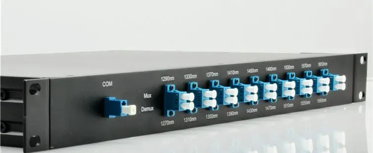
Thus, multiple 10G channels can be transmitted over a single fiber using different wavelengths.
Example 2. Connecting network nodes at a distance of up to 80 km
If you need to build a longer line, you can use CWDM modules with extended transmission range (40–80 km).
In this case, the scheme remains the same:
CWDM SFP → port of the corresponding wavelength on the MUX → trunk fiber → DEMUX → SFP.
If necessary, you can gradually add new channels by simply installing additional CWDM modules with different wavelengths.
Example 3. Trunk DWDM line
For more complex operator or trunk networks, DWDM technology is used. In such systems, each module corresponds to a specific channel of the ITU grid.
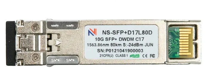
For example, a DWDM module on ITU channel 17:
When designing a line, it is important that:
the channel number of the DWDM module matches the channel of the multiplexer;
the optical budget of the line corresponds to the range of the module;
the equipment supports the required interface speed.
Such solutions allow organizing dozens of data transmission channels over a single fiber at distances of hundreds of kilometers.
❯ What are multiplexers and demultiplexers
Any system with уплотнением is built around two key devices – a multiplexer (MUX) and a demultiplexer (DEMUX).
A multiplexer combines several optical signals with different wavelengths into a single fiber.
A demultiplexer separates the signals back into individual wavelengths.
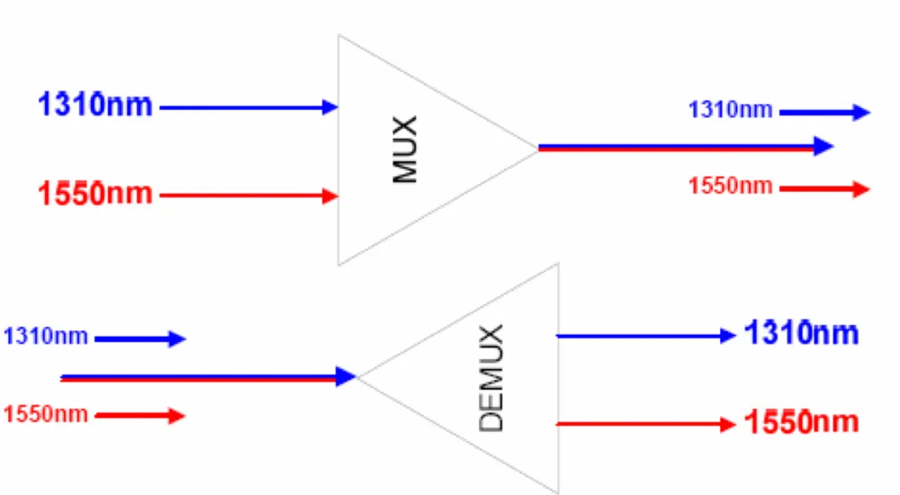
Although these concepts are distinguished, in practice, both of these devices are combined into one. They are called MUX/DEMUX or simply an optical multiplexer.
There are several technologies for implementing such devices. One of the most common is AWG.
❯ Arrayed Waveguide Grating
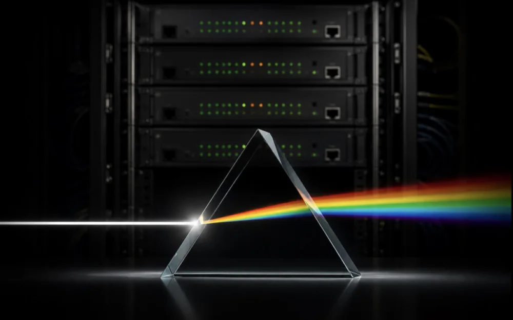
If you pass white light through a prism, it will split into a spectrum of colors.
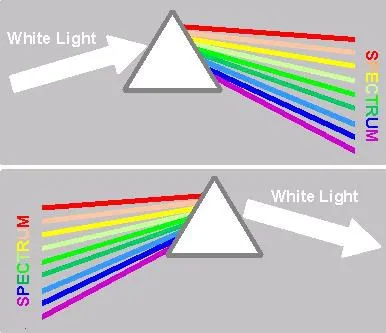
AWG (Arrayed Waveguide Grating) works on the principle of an ordinary prism, only instead of a glass prism, a microcircuit with a system of waveguides is used.
Light passes through an array of waveguides of different lengths. Due to differences in path length, interference of signals occurs, which allows separating or combining different wavelengths.
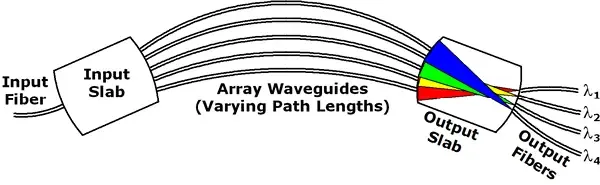
AWG modules are widely used in:
DWDM systems;
backbone networks;
optical transport platforms.
❯ FOADM and ROADM
In real networks, it is not always necessary to transmit all channels through every point of the network.
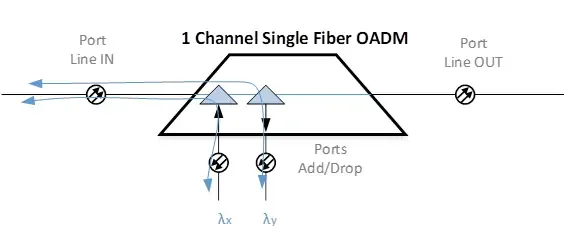
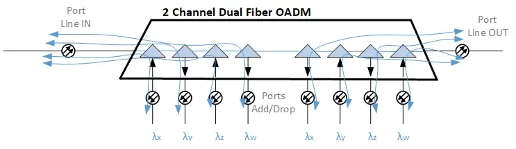
Sometimes it is necessary to send a pair of links to an intermediate communication node, while passing all the rest further along the backbone. Special devices called OADM modules are used for this purpose.
These modules are designed to organize the input/output of a signal at a specified wavelength from an optical group signal at intermediate nodes.
An OADM module, made of serially connected TTF filters, extracts a signal of a specific wavelength as it passes through these filters, while the remaining wavelengths of the group signal pass through the device transparently.
There are two types of OADM modules: unidirectional and bidirectional:
Unidirectional modules are used to extract/add signals from a line in one direction.
Bidirectional modules are used to extract/add signals from a line in one direction, and to extract/add signals to a line in the other direction. Moreover, the added wavelengths of the second direction may match the wavelengths of the first.
There are two main types.
FOADM (Fixed Optical Add-Drop Multiplexer) is a fixed configuration.
The following are defined in advance:
which channels are added;
which channels are extracted.
If it is necessary to change the network configuration, the equipment usually needs to be physically reconfigured.
ROADM (Reconfigurable Optical Add-Drop Multiplexer) is a more modern option.
It allows dynamic channel management without physical intervention.
With ROADM, you can:
redirect channels between different directions;
add new wavelengths;
change optical traffic routes.
In fact, such systems turn the optical network into a flexible software-controlled infrastructure.
❯ What to look for when choosing a WDM system
When it comes to full-fledged WDM line design, there are additional factors.
Optical budget
The most important factor. It shows whether the signal power is enough to traverse the entire line.
The calculation includes:
fiber attenuation (dB/km);
losses on splices;
losses on connectors;
losses on MUX/DEMUX;
losses on OADM.
The module must have power margin to compensate for these losses
Number of channels and scalability
Always take channels with a margin. It always seems that you've calculated everything and the channels will be enough. But after a year, a bunch of new services, another campus, and new requirements appear, and free channels remain tight.
You also need to build in a margin for scalability if the network will grow.
Therefore, WDM systems are always designed with a large channel margin.
❯ Conclusion
Previously, CWDM and DWDM technologies were used mainly by large telecom operators and backbone providers. Today, equipment has become much more affordable, and such solutions are increasingly applied in corporate networks, data centers, and infrastructure of large companies.
For small and medium networks, CWDM remains one of the most cost-effective ways to increase the bandwidth of an existing optical channel. DWDM, in turn, provides significantly greater scalability and is used where high channel density and long-distance data transmission are required.
Interestingly, many engineers use WDM technologies without even thinking about it. For example, modules QSFP+ IR4, QSFP+ LR4, QSFP28 CWDM4, and QSFP28 LR4 apply the principles of spectral multiplexing to combine multiple optical channels into one fiber.
Thanks to WDM technologies, modern optical networks are capable of transmitting hundreds of gigabits and even terabits of data over a single optical fiber.

Write comment