- DIY
- A
How to make a CI-V cable to control the Icom IC-R20 receiver
Hello, tekkix! This is Anton Komarov, the author of the MTS Digital special projects team. My interest in radio woke up a long time ago, ever since a friend showed me how useful it is to have a CB radio in the car to communicate with truck drivers. After working on the air, I became interested: what is happening on other bands? I began to gradually acquire UHF and VHF equipment and acquired a not very well-known RTL-SDR dongle based on Elonics e4000.
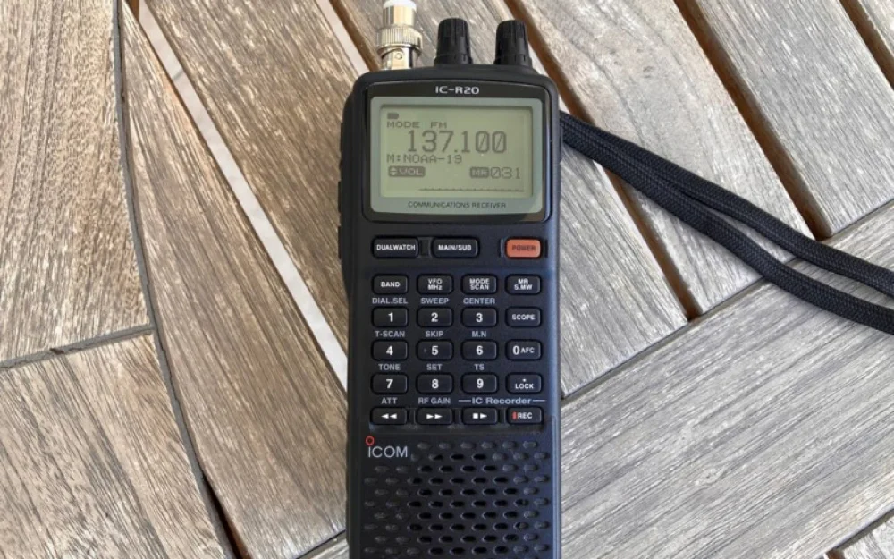
But the real event for me was a gift from a good friend who, seeing my desire to study radio, presented me with an Icom IC-R20 scanner. Even by today's standards, this is a cool device based on a superheterodyne with triple frequency conversion. It allows you to receive signals in the range from 150 kHz to 3,300 MHz, while having good sensitivity and selectivity. For now, I will not focus on its technical characteristics, but I will tell you about one of its features, namely remote control via the CI-V protocol.
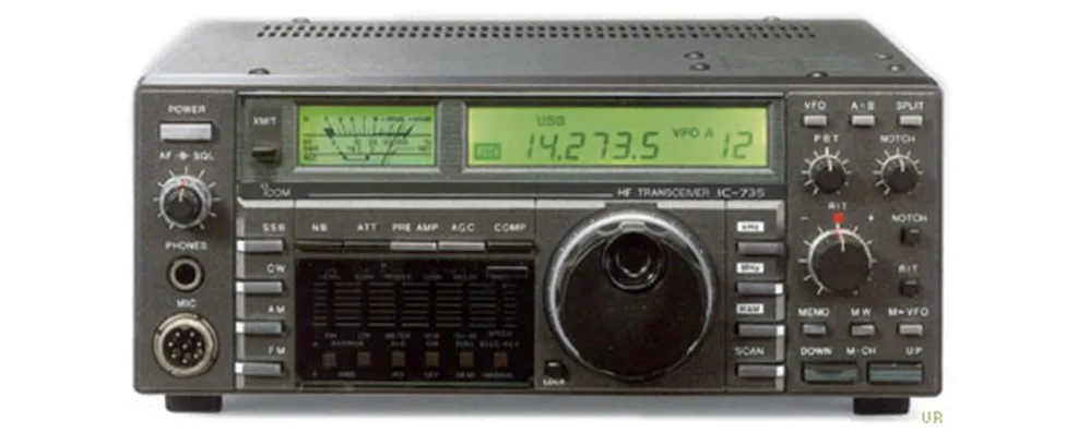
CI-V (Communications Interface V) was created by Icom in the early 80s and first debuted in the legendary IC-735 transceiver. Since then, Japanese engineers have carefully maintained backward compatibility, which ultimately made the protocol a standard for controlling Icom equipment. By the way, it is well documented: articles like this one are freely available on the network, which describe not only the physical interface but also the commands used.
Icom makes great equipment and supports many different accessories, including for remote control via CI-V. But as soon as you want to purchase any of them, you will be unpleasantly surprised by the cost. For the CT-17 adapter, which implements an RS232C to CI-V level converter and allows you to control up to four devices in a chain, you will be asked for 40 to 80 evergreen (plus shipping and tax depending on the country).
A single cable made by Uncle Liao will cost 19 $, which is already acceptable. But waiting for it from the same "Ali" can take quite a long time. Many prefer to assemble it themselves, fortunately, no expensive components are required. Before starting to create the cable, I will tell you what it is used for.
Application
Modern radio amateurs are increasingly working less with voice or Morse code, preferring more advanced types of communication such as FT8 or WSPR. The presence of remote control on the transceiver allows for automatic communication without an operator. Now a radio amateur can be hundreds of kilometers away from their equipment and still have full control over it.
But if the signal transmission is more or less clear, then why does a handheld radio scanner need CI-V? It would seem that it does not lack portability, it is not capable of transmitting anything, and the frequency can be set simply using a digital keyboard in a couple of seconds. But if you dig deeper, the support for remote control allows for the implementation of a feedback mechanism when receiving radio signals.
While you are going to the store for a pie or reading this article, the ISS is flying about 400 km above the earth. Quite often, experiments related to sending images via the SSTV protocol are conducted on the ISS. The frequency is known — 145.800 MHz, the pass can be calculated using special applications. It would seem, record the signal and then decode it, no difficulties.
The devil is in the details, as usual. At the moment when the ISS appeared on the horizon, the signal will be at a frequency of 145.8035 MHz. If you are lucky and the station is overhead, then at the moment of the pass the frequency is as stated, that is, 145.800 MHz. When the ISS disappears over the horizon again, the actual frequency will be 145.7965 MHz. It turns out that due to the Doppler effect, the difference is 7 kHz, which will undoubtedly affect the quality of the received image.
One way to eliminate the influence on reception is dynamic frequency hopping with a small step (1 kHz or less). There is special software that, having current TLE data (a set of orbital elements for an Earth satellite), can send commands to change the frequency during the pass, which allows for the highest quality reception of the useful signal. This is just one example of why such a receiver may require control via CI-V.
Protocol Features
Let's see what data transmission over the CI-V protocol looks like. Despite its similarity to AX.25, it is a separate entity that is incompatible with it.
The structure of any packet looks like this:
FE FE — preamble;
destaddr —destination address;
srcaddr —source address;
cmdcode —command code;
data1 .... dataN — data;
FD —ending byte.
Each Icom model has its own standard address in hexadecimal form. For the IC-R20, it looks like 6C. When you have just a single cable connecting one device to a computer, you don't need to change anything. But if you have the original CT-17 interface and several similar devices, each of them will need to be assigned a separate address.
Since the development of the standard, data exchange speeds have increased. Speed is an important setting that needs special attention. By default, my receiver is set to AUTO, which allows you to independently select the working value, depending on where it is connected and what maximum speed is supported on the other device. But you can also do it manually. Available options:
300 bps;
1 200 bps;
4 800 bps;
9 600 bps;
19 200 bps.
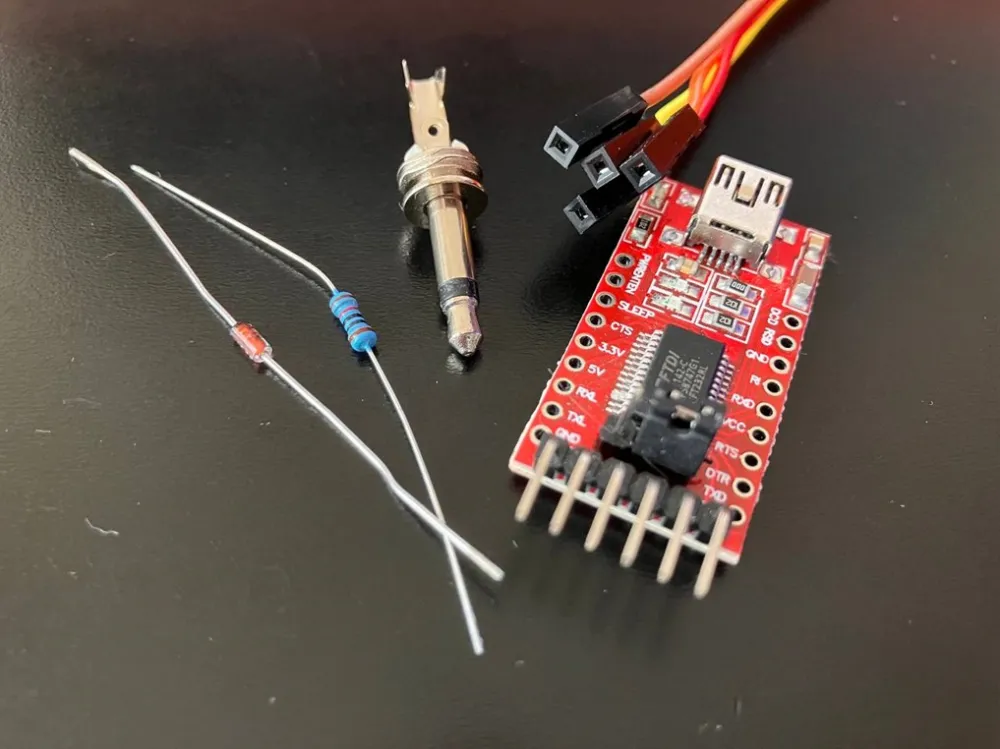
At the physical level, CI-V is a very ordinary TTL signal, where a voltage above 2V will mean one, and less than 0.8V — zero. So, if you take any ready-made USB-to-UART module, for example from FTDI, and make an adapter, then we will get the very cable we need. Note that the adapter level should be set with a jumper to 5 volts, not 3.3.
Scheme and manufacturing
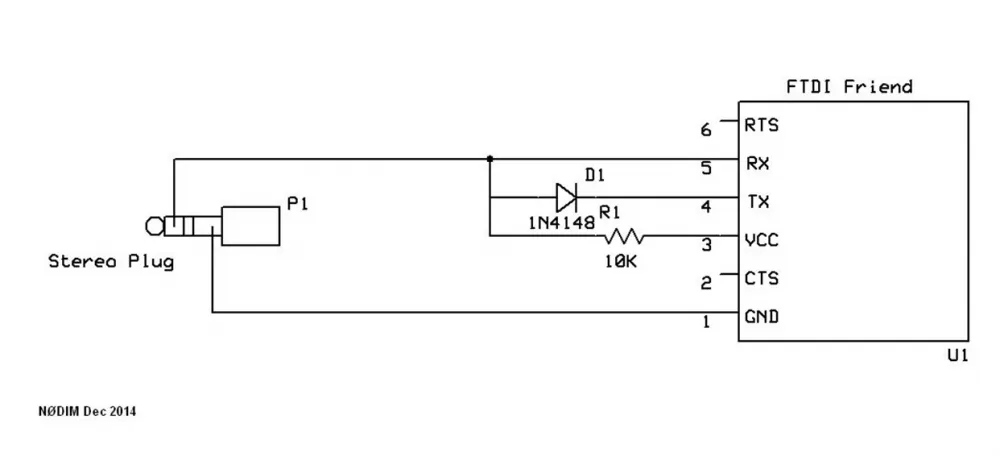
There has long been a circuit of an adapter on the network that can be assembled literally on the knee. It is suitable for working with most Icom transceivers and receivers:
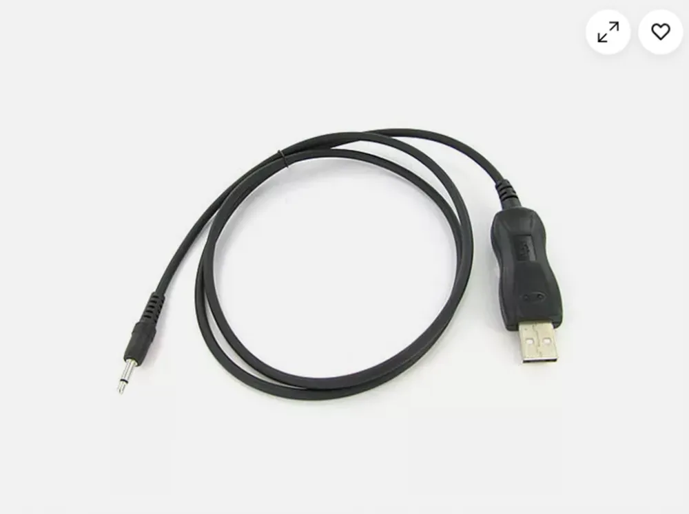
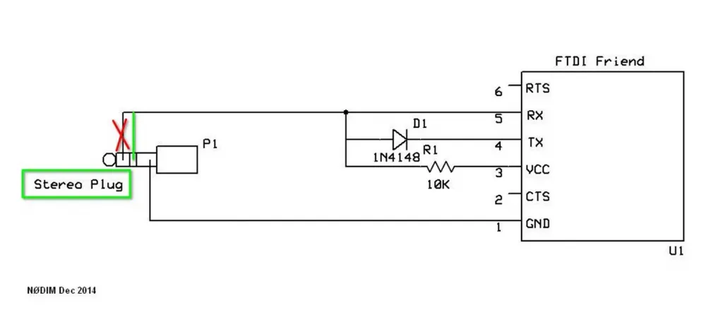
The scheme is simple: a silicon diode 1N4148, a 10 kOhm resistor, a 3.5” stereo jack, and some mounting wire. And here you will immediately be waiting for an unobvious trap. If you try to search the network for a ready-made cable, you will see this picture:
Here is not a stereo, but a mono jack 3.5”. This is what misled me, and I decided: if the Chinese cable has an audio connector, then I will take the same one. Said and done:
First test
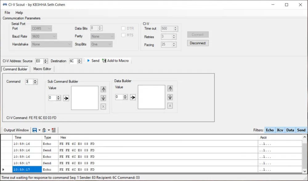
Ten minutes later, I had the assembled cable in front of me, and I immediately decided to test it using the CI-V Scout application, created by radio amateur KB3HHA Seth D Cohen. This small program allows you to form and send a set of bytes to a CI-V supported device, in response to which it should react and return information.
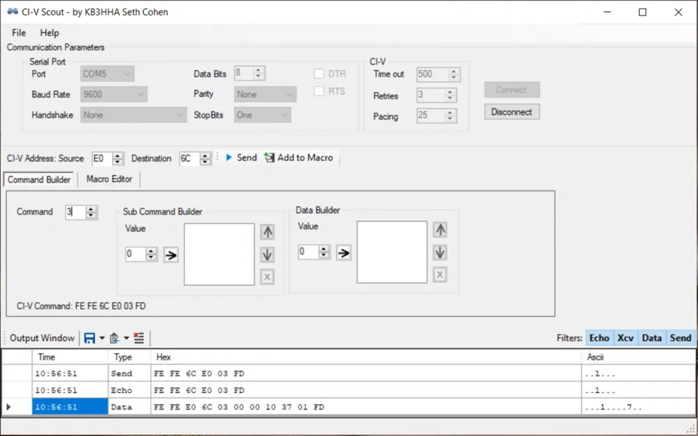
We select the virtual COM port number provided by the FTDI adapter driver, set the Baud Rate to 9,600, and then carefully check the addresses. In the CI-V Address: Source field, the default value should be E0. In the Destination field, we enter the address of our device 6C.
All that remains is to specify the command value in the Command field. We set the value to 3. In response, the receiver will return the current frequency to which it is tuned. In general, it looks like this:
FE FE 6C E0 03 FD
The response should be in the form:
FE FE E0 6C 03 {freq} FD
where {freq} is the frequency encoded in HEX. Press the Connect button and then Send to send the byte sequence:
The command was sent, the FTDI blinked happily with its lights, but in response, I only saw an echo and the message "Time out waiting for response to command Seq: 1 Sender: E0 Recipient: 6C Command:03."
There was no response, which means the cable is assembled incorrectly. And I suddenly realized that the CI-V and headphone jacks are the same. It turns out that with a mono jack, I definitely won't be able to get sound later, which makes the cable practically useless.
Solution to the problem
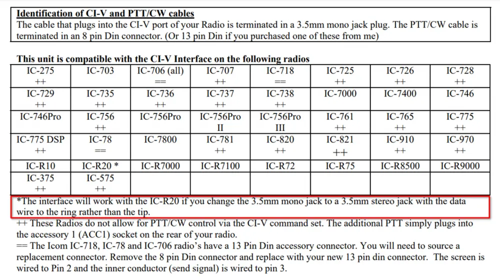
On large and serious transceivers, CI-V is separated from the audio output. Therefore, the proposed ready-made cables are built on a mono jack—they simply don't need more, and mono is always cheaper than stereo. But with the Icom IC-R20, the case is very special. While I was looking for what I did wrong, I found a file with a very interesting table and note:
It turns out that with the IC-R20, you need to not only use a 3.5" stereo jack but also change the pinout. RX should be on the center ring, not on the tip. The correct scheme looks like this:
In this variant, the tip serves for audio output paired with GND, and the data will go from the center ring. This is true exclusively for the IC-R20, such is the peculiarity of the model. So, taking the correct stereo jack and putting RX on the center ring, I tried to run CI-V Scout again:
Voila — everything works correctly, and in response to my command, the device reported the current frequency: 00 00 10 37 01, that is, 137.100 MHz.
It is also worth noting that it works in the opposite direction. The Icom IC-R20 itself can act as a "commander" and set parameters by sending them to the slave device. It can be either a computer or another transceiver and receiver.
To do this, press the 8 (SET) button, select the SET EXPAND item using the right knob (DIAL-R), place the cursor on ON and confirm again with the 8 (SET) button. Now there will be significantly more parameters in the settings section.
Scroll down and select the CI-V TRANSCEIVE item. Confirm the selection with the 8 (SET) button, place the cursor on ON and press 8 (SET) again. Now, when changing any parameters, whether it is frequency (or modulation), the corresponding commands will be sent to another connected device with the default address E0.
In conclusion
The use of a homemade CI-V cable is justified in most cases by its low cost. A USB-to-UART adapter costs $2.5. The connector, diode, and resistor cost another $1. I do not take the cost of the wire into account: it can be taken from anywhere. It turns out that for $3.5 and 10 minutes of time, you will assemble a cable that costs $19 in finished form and implies a month of waiting. Plus, if you are the proud owner of an IC-R20, then this cable with a mono plug will not suit you either — then you will have to cancel the order and request a refund.
Well, if you have not a single transceiver, but several, it is worth either assembling many such cables or already thinking about buying an original accessory. Although, it seems to me, it will be possible to make a homemade one based on Arduino at a ridiculous cost. Or even on a Raspberry Pi Zero with output to the screen and the ability to set parameters for each transceiver separately. If I assemble such a setup, I will definitely share it with you. And that's all for today.
I would be glad if you share your own homemade products in the comments.




Write comment