- DIY
- A
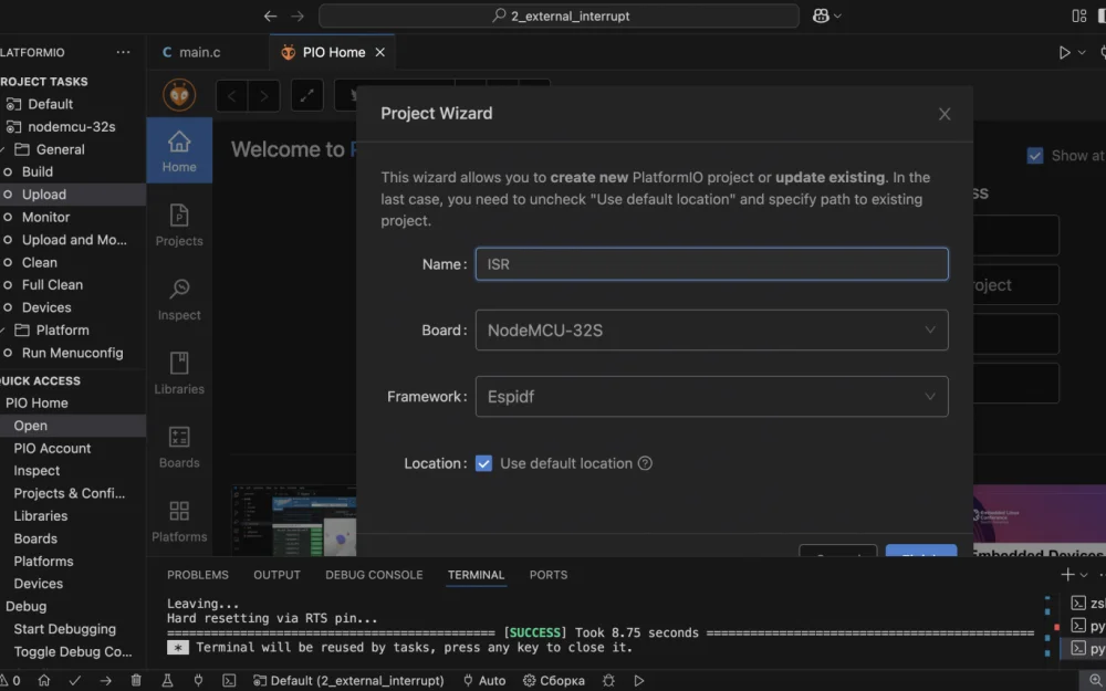
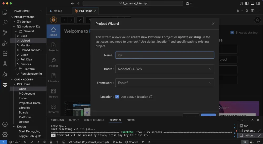
Programming ESP32 with ESP-IDF in PlatformIO environment #1
Hello, tekkix!
This is the second article in the series on programming ESP32 using ESP‑IDF. In the first part, we introduced basic RTOS terminology and implemented a few simple tasks. Today, we’ll move on to working with GPIO and interrupts (ISR), and also discuss the specifics of task stack configuration in ESP‑IDF (thanks for the tip @0x6b73ca).
Stack
Let’s turn to the official documentation:
FreeRTOS
In FreeRTOS, we work in words.
ESP-IDF
In ESP-IDF, we work in bytes.
In classic FreeRTOS, the usStackDepth parameter is specified in machine words (StackType_t), whereas in ESP‑IDF, the same parameter is measured in bytes. It’s important to take this into account when porting projects between platforms to avoid allocating too much or too little memory for the task stack.
GPIO
By default, each physical contact (pad) of the ESP32 can perform various hardware functions — from ADC and touch sensors to UART, SPI, and LED controllers. To use a pad as a standard digital I/O, it needs to be switched to GPIO mode.
For this, the function is used
esp_rom_gpio_pad_select_gpio(pin);It disables all alternative functions (ADC, touch, UART, SPI, LEDC, etc.) and binds the selected pad to the GPIO module.
Next, you can set the direction and levels using standard APIs. Below are the main functions for working with GPIO:
Main functions when working with GPIO |
Function | Description |
|---|---|
| Binds a physical pad to the GPIO module, disabling all alternative functions of the contact. |
| Resets the pin configuration to the default value (calls |
| Sets the direction: |
| Sets the logical level (0 or 1) on the output pin. |
| Reads the current logical state (0/1) of the input or output pin. |
| Simplified group configuration: direction, pull-ups, interrupts, pin mask. |
| Enables or disables the internal pull-up resistor. |
| Enables or disables the internal pull-down resistor. |
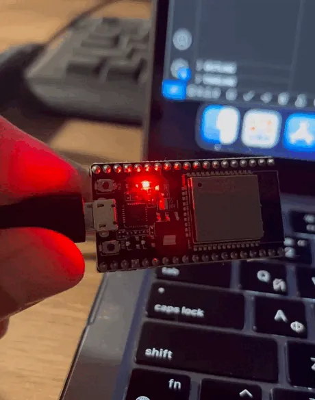
Let’s blink)
And what are we blinking with?
On the NodeMCU‑32S board (and many other "devkit" modules for ESP32), the built-in LED is physically connected to the GPIO2 pin. Let's also declare the task descriptor for blinking:
#define LED_GPIO GPIO_NUM_2 // LED pin
TaskHandle_t Blink_Handle = NULL; // Blink task descriptor
Blink_Task
I think we have discussed the task mechanism in enough detail in the previous article, so without further explanation, here’s the final structure of the task:
void Blink_Task(void *arg){
    esp_rom_gpio_pad_select_gpio(LED_GPIO); // "Switch" the selected physical pin to GPIO mode
    gpio_set_direction(LED_GPIO, GPIO_MODE_OUTPUT); // Set direction as output

    while(1){
        gpio_set_level(LED_GPIO, 1);        // Set logical level 1
        vTaskDelay(pdMS_TO_TICKS(1000));    // Wait
        gpio_set_level(LED_GPIO, 0);        // Set logical level 0
        vTaskDelay(pdMS_TO_TICKS(1000));    // Wait
    }
}
Result
#include "freertos/FreeRTOS.h"
#include "freertos/task.h"
#include "driver/gpio.h"

#define LED_GPIO GPIO_NUM_2 // LED pin

TaskHandle_t Blink_Handle = NULL; // Blink task descriptor

void Blink_Task(void *arg){
    esp_rom_gpio_pad_select_gpio(LED_GPIO); // "Switch" the selected physical pin to GPIO mode
    gpio_set_direction(LED_GPIO, GPIO_MODE_OUTPUT); // Set direction as output

    while(1){
        gpio_set_level(LED_GPIO, 1);        // Set logical level 1
        vTaskDelay(pdMS_TO_TICKS(1000));    // Wait
        gpio_set_level(LED_GPIO, 0);        // Set logical level 0
        vTaskDelay(pdMS_TO_TICKS(1000));    // Wait
    }
}

void app_main() {
    xTaskCreate(
        Blink_Task,     // Pointer to the task function
        "BLINK",        // Task name (for debugging)
        4096,           // Stack size
        NULL,           // Argument passed to the function (not needed here)
        10,             // Task priority
        &Blink_Handle   // Pointer to where the task descriptor will be stored
    );
}
Interrupts (ISR)
Interrupt is one of the basic concepts in computing, where upon the occurrence of some event, control is transferred to a special procedure called the interrupt handler (ISR).
Interrupts can be of two types:
Hardware — generated by hardware (e.g., peripheral GPIO modules, timers, UART);
Software — initiated by executing a special instruction in the code that "artificially" calls the handler.
Additionally, the ESP32 implements an Inter-Processor Call (IPC) mechanism, which has two operating modes:
Task Context — the callback is executed in the context of a special IPC task, allowing the use of any FreeRTOS and ESP-IDF functions.
ISR Context — the call occurs immediately in the context of a high-priority interrupt (Inter-Processor Interrupt). In this mode, the callback must reside in IRAM and be implemented in assembly, as it is not possible to rely on the availability of flash cache, and only low-level instructions are supported.
Details and limitations of each mode can be found in the official IPC documentation:
https://docs.espressif.com/projects/esp-idf/en/stable/esp32/api-reference/system/ipc.html
Registering an Interrupt Handler in ESP-IDF
Below are the main functions and their attributes when working with ISR:
gpio_set_intr_type(gpio_num, intr_type);Purpose: sets the interrupt type (on which edge) for a specific GPIO pin.
Parameters:
gpio_num– pin number (GPIO_NUM_0…GPIO_NUM_39).intr_type- interrupt type:GPIO_INTR_DISABLE- disable interruptGPIO_INTR_POSEDGE- on positive edgeGPIO_INTR_NEGEDGE- on negative edgeGPIO_INTR_ANYEDGE- on any edgeGPIO_INTR_LOW_LEVEL- on holding low levelGPIO_INTR_HIGH_LEVEL- on holding high level
In the context of GPIO interrupts, the term "edge" refers to the moment of signal level change, and "level" refers to the actual fact of holding the signal at a particular state. For example,
GPIO_INTR_POSEDGE("on positive edge") triggers once when the input signal transitions from 0 to 1 (low → high).GPIO_INTR_ANYEDGE("on any edge") triggers both on 0→1 and 1→0 transitions.
gpio_install_isr_service(intr_alloc_flags);Purpose: initializes the GPIO interrupt service, allowing the registration of handlers (
gpio_isr_handler_add) for specific pins.Parameter
intr_alloc_flags:0– no special flags (priority and mode are determined by the system)ESP_INTR_FLAG_IRAM- interrupt handlers will be loaded into IRAMESP_INTR_FLAG_LOWMED- medium / low interrupt priority
When using the
ESP_INTR_FLAG_IRAMflag ingpio_install_isr_service(), you ensure that:
The interrupt handler (ISR) you later register will be called from IRAM.
All internal structures and ISR call routing will also be placed in IRAM.
This is necessary because during some interrupts (e.g., related to SPI Flash or DMA) the cache may be disabled, and code in flash memory will become unavailable. If a jump to an address in flash occurs at this moment, it will result in a crash, watchdog reset, or undefined behavior.
For those who forgot or didn’t know:
IRAM (Internal RAM) is the fast internal memory inside the ESP32. It operates faster and does not depend on external SPI Flash, which is critical for the reliable and fast operation of interrupt handlers.
gpio_isr_handler_add(gpio_num, isr_handler, args);Purpose: registers an interrupt handler function (
isr_handler) for a specific GPIO pin.Parameters:
gpio_num— pin number (GPIO_NUM_0…GPIO_NUM_39)isr_handler— pointer to the interrupt handler functionargs— arbitrary argument passed to the handler function
gpio_intr_enable(gpio_num);Purpose: enables interrupts for the specified GPIO pin.
Parameter
gpio_num— GPIO pin number.
The interrupt will not trigger unless you call this function (or disable it previously).
gpio_intr_disable()- disables the interrupt.
// interrupt handler function
void IRAM_ATTR gpio_isr_handler(void* arg) {
}
IRAM_ATTR is an attribute (basically a decorator) that guarantees this code will go into fast IRAM, not flash.
If you have a question (just in case ¯\_(ツ)_/¯): “Why do we need IRAM_ATTR if there is already ESP_INTR_FLAG_IRAM?”, I’ll try to answer.
The ESP_INTR_FLAG_IRAM flag forces the system to use a handler located in IRAM — but it does not actually move your function there! For the compiler to actually place the interrupt handler in IRAM, you have to explicitly specify it — using IRAM_ATTR.
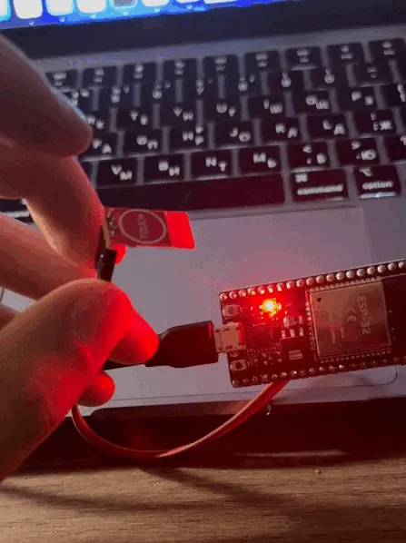
Practice
Our goal is to implement an interrupt from a button, which will toggle the logical state of the LED. To do this, let's slightly rework the Blink_Task we wrote at the very beginning:
uint8_t state = 0;                // Variable storing current LED state (0 – off, 1 – on)

TaskHandle_t Blink_Handle = NULL; // Descriptor for the Blink task

// Task that constantly sets the LED_GPIO level according to state
void Blink_Task(void *arg) {
    while (1) {
        gpio_set_level(LED_GPIO, state);
    }
}
Now we just need to implement the actual interrupt handler that will change the state. The function turns out pretty compact:
/*
    Button interrupt handler.
    Simply inverts the state variable.
    IRAM_ATTR is an attribute that ensures this code lands in fast IRAM,
    not flash (this is important for ISR reliability).
*/
static void IRAM_ATTR gpio_isr_handler(void *arg) {
    state = !state;
}
Now it's important to properly register the interrupt handler. Here’s the procedure:
Set the interrupt type:
gpio_set_intr_type(gpio_num, intr_type);Initialize the general ISR service:
gpio_install_isr_service(intr_alloc_flags);Register the interrupt handler for the required pin:
gpio_isr_handler_add(gpio_num, isr_handler, args);Enable interrupts for the pin:
gpio_intr_enable(gpio_num);
#include "freertos/FreeRTOS.h"
#include "freertos/task.h"
#include "driver/gpio.h"

#define LED_GPIO    GPIO_NUM_2     // Pin to which the LED is connected
#define BUTTON_GPIO GPIO_NUM_23    // Pin to which the button is connected

uint8_t state = 0;                 // Variable storing the current state of the LED (0 – off, 1 – on)

TaskHandle_t Blink_Handle = NULL;  // Blink task handle

// Task that constantly sets the level on LED_GPIO according to state
void Blink_Task(void *arg) {
    while (1) {
        gpio_set_level(LED_GPIO, state);
    }
}

/*
    Button interrupt handler.
    Just inverts the state variable.
    IRAM_ATTR — attribute that guarantees this code will be placed in fast IRAM,
    not in flash (important for ISR reliability).
*/
static void IRAM_ATTR gpio_isr_handler(void *arg) {
    state = !state;
}

void app_main() {
    esp_rom_gpio_pad_select_gpio(LED_GPIO);          // "Switch" the selected physical pin to GPIO mode
    gpio_set_direction(LED_GPIO, GPIO_MODE_OUTPUT);  // Set LED_GPIO as digital output

    gpio_set_level(LED_GPIO, 0);   // immediately turn off

    esp_rom_gpio_pad_select_gpio(BUTTON_GPIO);          // "Switch" the selected physical pin to GPIO mode
    gpio_set_direction(BUTTON_GPIO, GPIO_MODE_INPUT);   // Set BUTTON_GPIO as input

    gpio_pullup_en(BUTTON_GPIO);    // Pull-up to VCC

    gpio_set_intr_type(BUTTON_GPIO, GPIO_INTR_POSEDGE); // Interrupt on button press (rising edge)

    gpio_install_isr_service(ESP_INTR_FLAG_IRAM);       // Set up ISR service

    gpio_isr_handler_add(BUTTON_GPIO, gpio_isr_handler, NULL);  // Register ISR handler function

    gpio_intr_enable(BUTTON_GPIO);  // Enable interrupts for the button

    // Create a task that will "blink" the LED according to state
    xTaskCreate(
        Blink_Task,       // task function
        "BLINK",          // name (for debugging)
        2048,             // stack size (bytes)
        NULL,             // task parameter
        5,                // priority
        &Blink_Handle     // task handle will be written here
    );
}
In fact,
gpio_intr_enable()doesn't need to be called)This function is optional if you use
gpio_isr_handler_add(), since it enables the interrupt internally anyway.
Conclusion
If you notice any inaccuracies, errors, or have suggestions for improving the article — feel free to write in the chat or comments. I’ll be happy to adjust the material so it’s more helpful for everyone learning ESP-IDF.
In the next parts, we’ll continue to explore ESP-IDF: and will look at working with PWM and the ADC (analog-to-digital converter).


Write comment