- Network
- A
IPsecHub+. Segmentation on the IPsec hub
Hello everyone! This is Nikolai Yedomskiy, the head of the network engineering team at EDINOM TSUPIS.
I present to your attention the second article in the "IPsecHub+" series.
The first article of the series is here. In the first article, we delved a little into the specifics of our technology stack, and now let's look at the classic scenario of building a GRE-over-IPsec tunnel. This will be the first step toward implementing our “IPsecHub+” solution.
So, let's get right to it. Let's imagine that we need to connect two branch offices to the data center (in the south) over the Internet (in the north).
The Challenge of Building an IPsec Hub
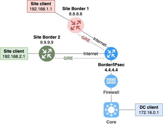
As in the case described in the first article, in this simplified topology, the border routers also serve as IPsec terminators. They have addresses configured on their WAN interfaces that are routed in the Internet ("public" addresses). See fig. 1.
Let's think about what might not satisfy us about this topology?
No possibility for firewalling. The IPsec concentrator is directly connected to the Internet, so we cannot centrally restrict traffic from the Internet to the IPsec concentrator and back. Not to mention the implementation of IPS/IDS and other advanced security tools.
Risk of critical load on the border router's resources. IPsec is a rather resource-intensive protocol stack. Its active use can cause problems with the entire border router, negatively affecting all services it serves. That is, potentially the entire company, if we are talking about the data center router.
Difficulty scaling IPsec. If we need to increase IPsec resources, this requires replacing the entire border router, even if it's perfectly sufficient as a router. We'll call this vertical scaling.
The most critical drawback, of course, is the firewalling issue. Let's deal with them first. We might end up with something like this. See fig. 2.

In this case, the IPsec concentrator is placed as a separate node below the border segment. The above-mentioned design flaws are eliminated. We control incoming and outgoing encrypted traffic to the IPsec concentrator with a firewall.
But a new problem arises. Decrypted traffic from the branches no longer passes through the firewall. Not good. Any station in a branch now has direct access to the data center.
To solve this issue, we can build this type of scheme. We'll place the IPsec concentrator behind the firewall. See fig. 3.
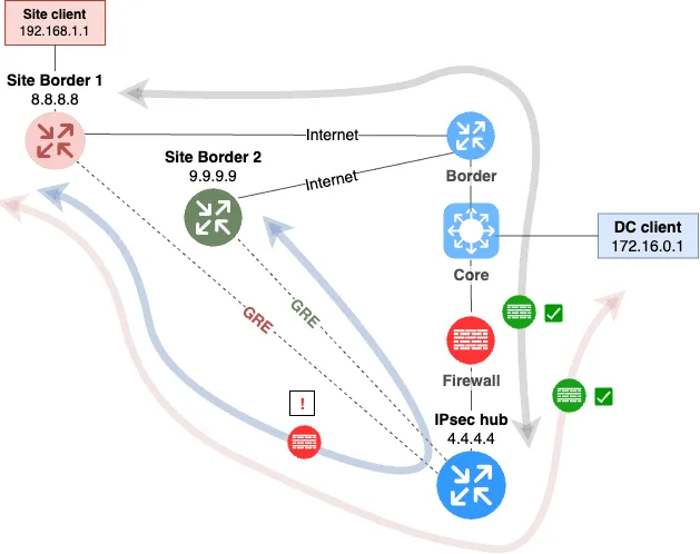
The decrypted traffic will go through the firewall. However, the information security department says, that we also need to route the traffic between the branches to the firewall. The situation becomes complicated. Since all GRE and VTI tunnels are located on a single IPsec concentrator, which in fact is also a router, the traffic between them is routed via connected routes. The traffic will not be directed to the firewall.
We will not consider PBR and other source routing technologies as a solution to this problem, because it will significantly complicate the configuration, and not all IPsec concentrators support PBR or its analogs.
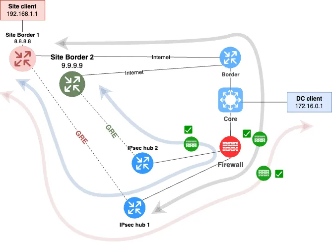
The task of firewalling the "branch-branch" direction can be solved by allocating a separate IPsec concentrator for each of the branches. The scheme is shown below, see Fig. 4.
As a result, we firewall:
Incoming and outgoing encrypted traffic to the IPsec concentrator.
Decrypted traffic from the IPsec concentrator to the data center.
Traffic between the branches.
In this case, the firewalling issue is solved. The IPsec concentrator of each branch is connected to the firewall, and the only path for the "branch-branch" direction goes through the firewall.
This scheme solves all the firewalling tasks. However, it has serious drawbacks.
It scales very poorly. If there are many branches, and we allocate one concentrator for each branch, then each IPsec concentrator in the data center will need to be allocated an external address, which is quite wasteful.
A large number of virtual machines will create additional load in terms of administration and monitoring.
It is hard to implement fault tolerance. There will already be many concentrators, and if they are multiplied by two...
Looking ahead, this scheme will not allow using bare-metal IPsec with all its advantages.
The drawbacks are quite serious. We will not consider it as the main development vector, we need to find another path.
Objective setting
Let us now formalize all the requirements for the design that we need to create.
Traffic between the branches must pass through a centralized firewall.
Encrypted traffic between the data center and the branches must pass through a centralized firewall.
Tunnels must terminate on a single IPsec concentrator.
The solution must be scalable.
The solution must be fault-tolerant.
The solution must be flexible and manageable.
The solution must not be proprietary.
The solution must be technically flexible and support various types of tunnels in different configurations (VTI, GRE…).
The solution must support dynamic routing.
The solution must not involve the firewall in dynamic routing.
About the last requirement, I will say separately. After gaining extensive experience with various NGFW operations, we concluded that involving NGFW in dynamic routing processes creates far more problems than it brings benefits. Perhaps "we just don't know how to configure them," but still. We decided to categorically abandon the use of BGP, OSPF, and other dynamic routing on the firewall. This requirement was dictated by the analysis of many incidents, working with vendor support, and generalizing all this experience. We concluded that the firewall should only operate on static routing.
Segmentation
Let's start with the search for a conceptual solution to our main task, which we solved in the previous example in a less elegant way - the task of isolating traffic between branches.
As mentioned above, a solution to diverting traffic to the firewall within a single routing table could be technologies like PBR (+ route tables, etc.). But this would significantly complicate the configuration and nullify all the advantages of dynamic routing. Moreover, not all IPsec concentrators support PBR as such. We are looking for a universal solution.
Let's look towards solutions that involve using different routing tables - let's try to place the branch tunnel interfaces in different tables.
But here we need to consider one nuance. Placing GRE tunnels into separate VRFs doesn’t seem to be anything difficult. But we don’t place IPsec tunnels into any VRFs. They all land in one VRF (default in this case) on a single IP address. So, how will this work?
The main trick of this solution is that you can keep the IPsec tunnel in the main routing table, and move the GRE tunnel, which is encrypted by this IPsec, to another VRF. This approach is supported by a number of operating systems. For example, Cisco IOS and Linux/Unix system implementations.
This scheme is possible because the IPsec daemon creates a traffic interception trap at a level below the logical traffic distribution into VRFs. This means that the IPsec daemon will intercept traffic matching its encryption lists, even if this traffic was generated within any user VRF.
Graphical Representation of VRF
A few words about visualization. I didn’t find any ready-made visualization schemes from vendors that would allow for simply and clearly displaying the VRF structure on the device, as well as the connections between different VRFs. I decided to present the following conditional notations. All further constructions and diagrams will be based on this visualization.
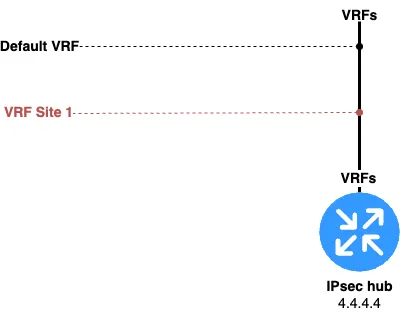
For schematic representation of VRF on any router, we will use horizontal lines extending from a vertical line. See fig. 5.
And this is what, for example, the immersion of multiple interfaces into the "red" VRF would look like. See fig. 6.
With the adopted graphical representation, I was able to visualize even quite complex interaction schemes between different VRFs created on different devices.
Building the basic topology of the hub
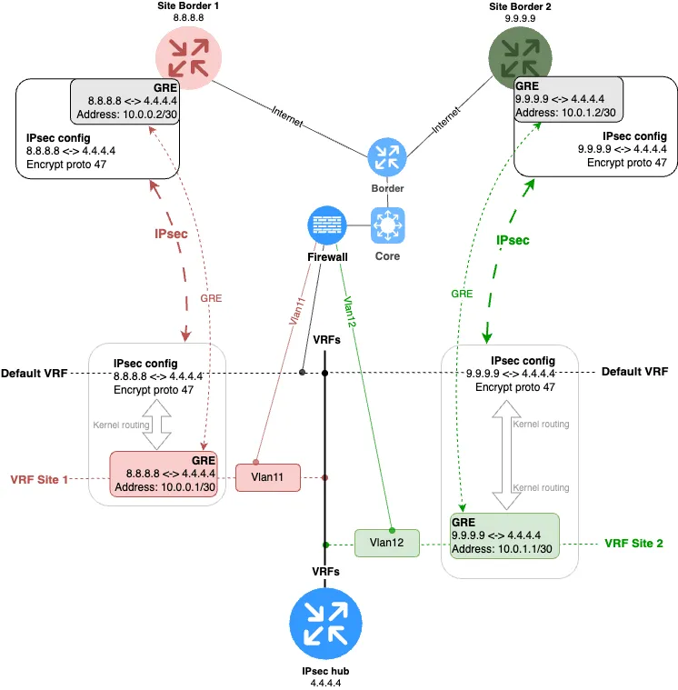
So, let’s get back to practice and build a topology where the IPsec tunnel will be located in the default VRF (or, in other words, it won’t be in any VRF), and the GRE tunnel, which is encrypted by this IPsec tunnel, will be placed in the “red” VRF.
The resulting diagram is shown in Fig. 7.
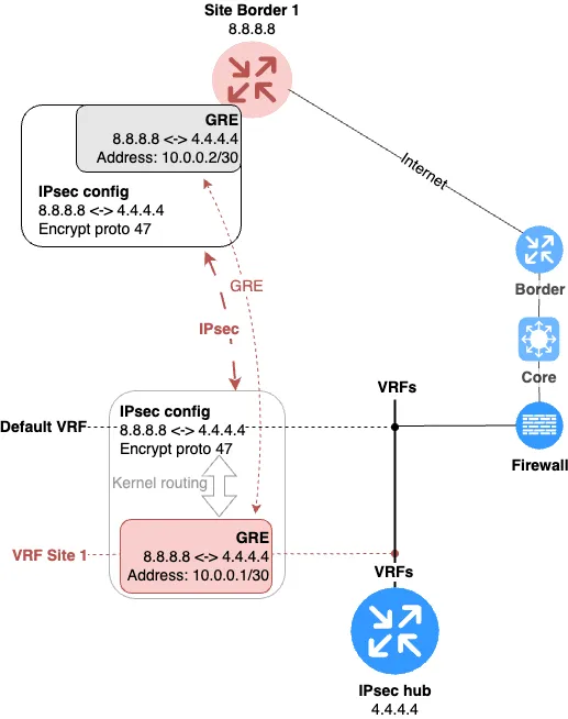
So, what exactly did we do?
Created a GRE tunnel between the IPsec hub with endpoints 4.4.4.4 (Data Center) and 8.8.8.8 (branch office).
Assigned the GRE interface to a separate VRF, which we named “Site 1”; on the diagram — the “red VRF”.
Encrypted this tunnel via IPsec in the default VRF. As a result, the branch IPsec hub will encapsulate all traffic intended for the GRE tunnel into GRE datagrams, then these datagrams will be encrypted. At the data center, the datagram is decrypted, and the traffic encapsulated in GRE is decapsulated inside the desired VRF.
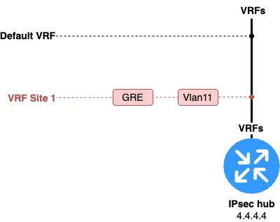
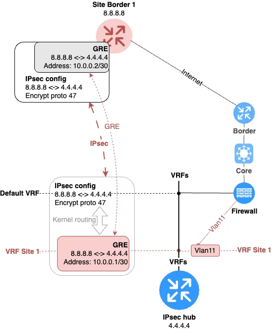
Okay, but how do we organize interVRF routing in this design? That’s simple. On the IPsec hub, we just need to create one VLAN interface for each VRF and assign them to the corresponding VRFs. With classic switching, we send these VLANs to the firewall, where corresponding VLAN interfaces are also created. The topology is shown in Fig. 8.
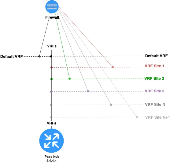
Here is what connecting a second branch will look like. See Fig. 9.
This design solves all the stated tasks. I propose the reader independently trace all possible traffic directions and make sure all flows pass through the firewall.
But where might the problem be? Strangely enough, it might be the number of VLAN interfaces that need to be created on the firewall when adding each new branch to the network. But more specifically, the problem is that the firewall is involved at all in either the creation or the removal process of a branch.
Scalability features
All tasks in terms of traffic filtering in all directions are accomplished. Traffic between branches will always go through the firewall, since it basically acts as an inter-VRF router. But there is one unpleasant feature to this scheme — it doesn’t scale well at the firewall level. Imagine you need to connect a fairly large number of branches to the hub. That number could increase or decrease every month. For example, this can happen if you decide to use a cloud provider and want to connect many VPSs (virtual private servers) or VPCs (virtual private clouds) to your data center within this scheme.
Given these inputs, it turns out that we need to constantly add, in addition to GRE interfaces, also the connecting vlan interfaces on the concentrator, which link the target VRFs to the firewall, as well as create these interfaces on the firewall itself. With a small number of VRFs, this may not cause major difficulties. But if VRFs need to be added (or removed) every week, it becomes clear that:
this process is better to automate
it’s better to exclude the firewall from this process altogether.
Adding an interface is quite a risky operation when it comes to the company’s central firewall. Practical experience has shown that sometimes these operations lead to a cumulative effect, which may eventually result in very unpleasant consequences. Also, on some firewalls, the number of subinterfaces is limited.
As a result, we have formed an additional goal - to localize routine processes as much as possible. That is, to concentrate them, if possible, on the IPsec concentrator itself.
The next article in the series will be dedicated to achieving this goal. Thank you for your attention, and see you next time!


Write comment