- DIY
- A
How I made a CO2 sensor for a smart home based on SCD30
I have two beloved sisters who would very much like to have a temperature, humidity, and carbon dioxide sensor at home. The ready-made solutions available on the market did not suit me at all, and as they say: if you want to do it well, do it yourself.
Component selection
I used MH-Z19 carbon dioxide sensors and SHT31-D temperature and humidity sensors, which were mounted on an ESP32.
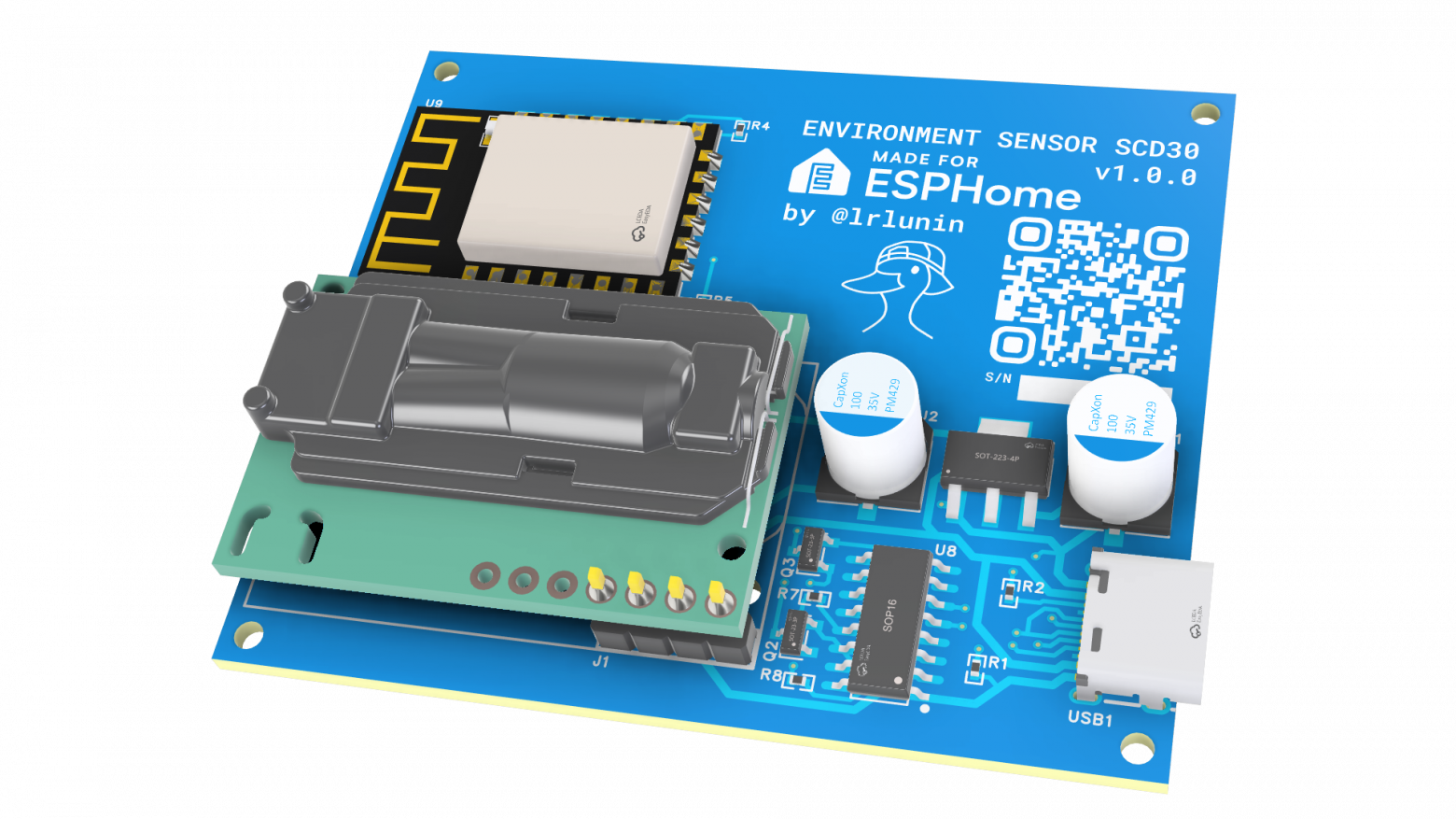
I was looking for a sensor that would ideally have a more convenient form factor and, if possible, combine all three characteristics. In the list of supported sensors on the ESPHome website, I found the SCD30 from Senserion.
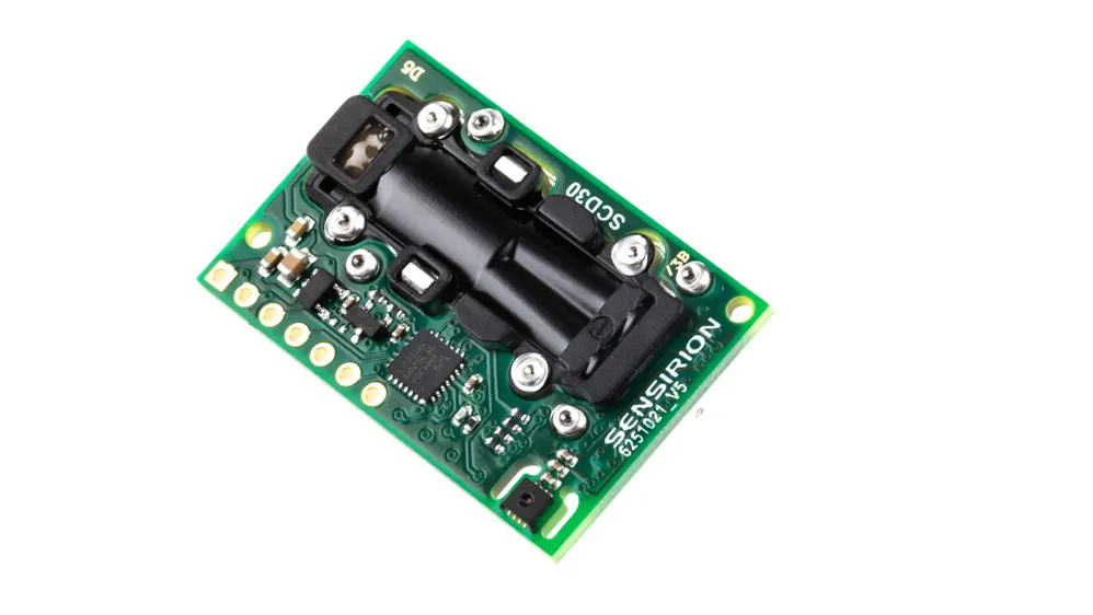
In addition to the compact size and positive reviews on the forums, the price of around $15 per piece was also pleasantly surprising.
As a controller, I decided to use the ESP8266 due to the lack of need for Bluetooth and the use of a single I2C device.
Since the device will be used by people far from the world of microcontrollers and electronics, it was decided to use USB-C for the device and equip each board with a built-in USB-UART converter for firmware uploading. Here I would like to draw attention to the ESPHome ecosystem again, where the firmware is configured with a yaml file, compiled, and uploaded by a Python program automatically. Moreover, it works on Windows, MacOS, and Linux without any problems.
Board development
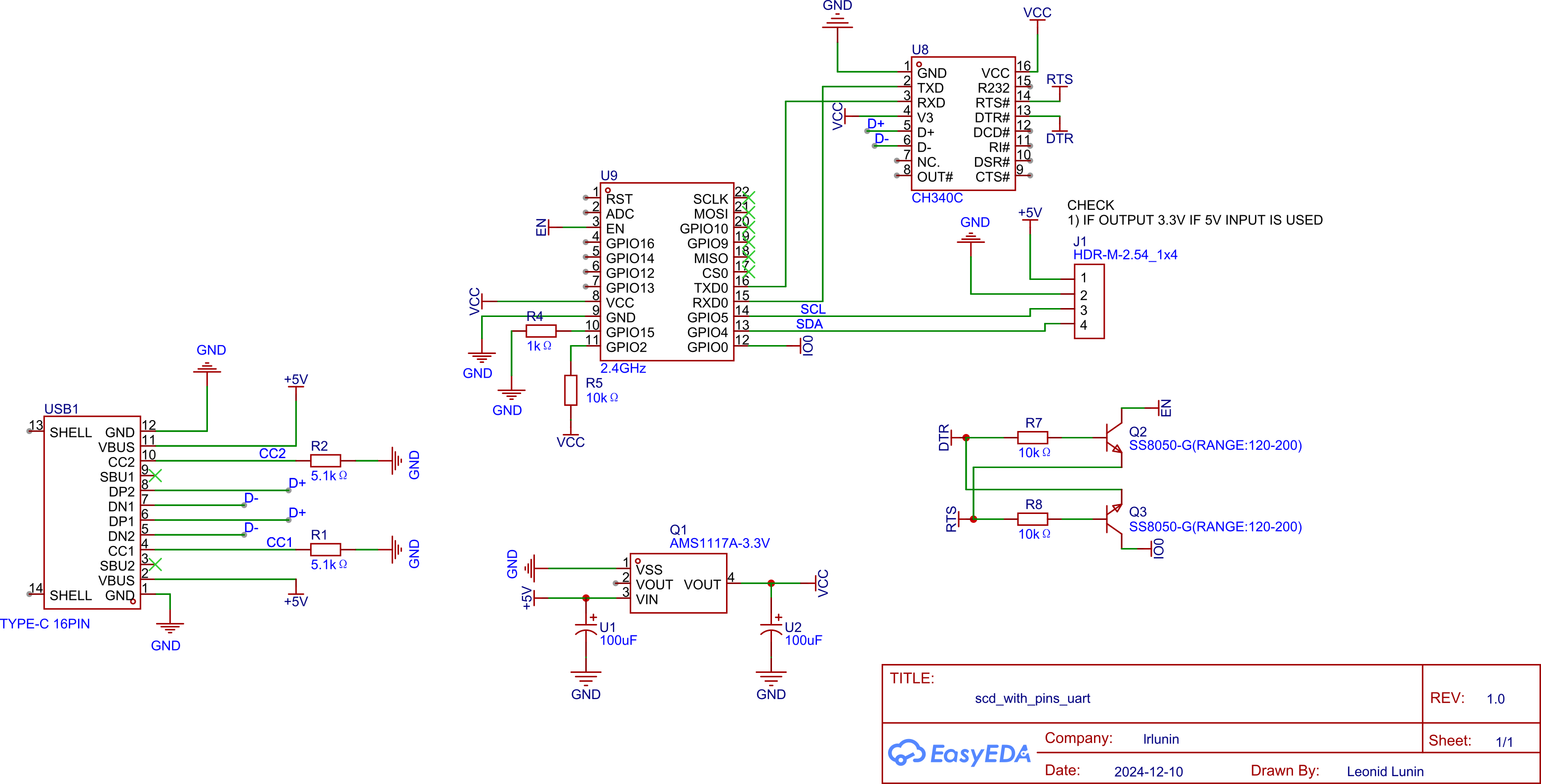
Since it was originally planned to order boards from JLPCB, I decided to use their EasyEDA Pro environment (which is free just like the standard version).
For the UART converter connection scheme, references from the official ESP documentation were taken. The use of RTS and DTR pins with two transistors allows the firmware loader to reboot the board into firmware mode without active user participation.
Then I tried about 5 different layouts of the elements and settled on the following:
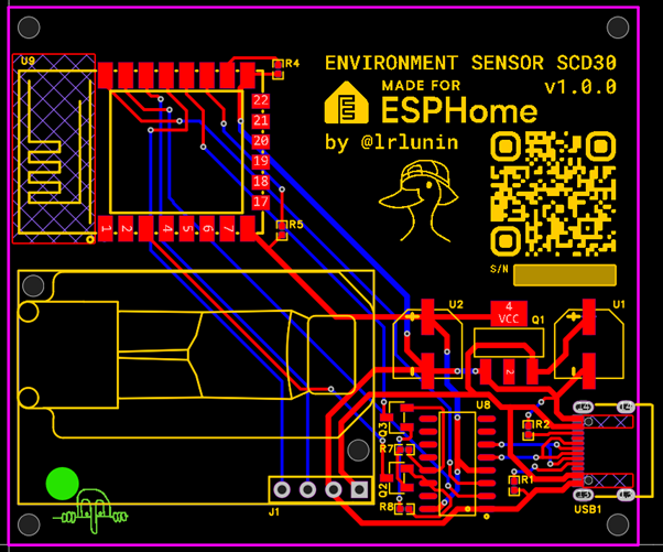
The main motivation for this layout was two reasons:
Maximum removal of the SCD30 temperature sensor from the ESP8266, located on the underside of the sensor board, at the location of the green circle
Positioning the sensor below the controller, in the vertical orientation of the device (with USB-C at the bottom of the device) to avoid temperature distortion from the warm convection flow from the ESP8266
It was also interesting to see if the convection effect would play any significant role in air circulation. To do this, I ran a simulation in Autodesk Fusion for horizontal and vertical layout of the circuit in a case with holes.
Airflow simulations
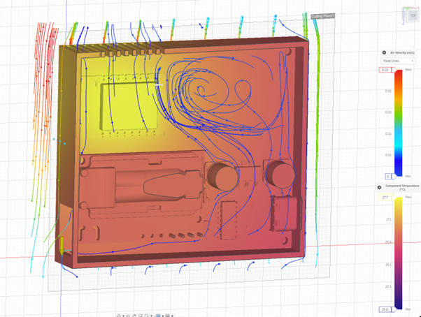
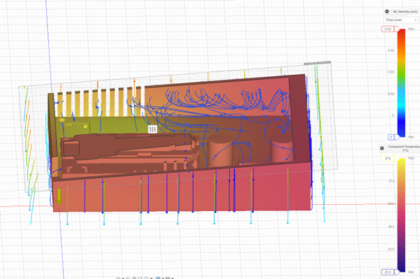
The temperature effect from heating did not differ from the orientation of the board, and the air flow rate differed insignificantly (as expected). However, I am not sure if the simulation can be considered plausible for such low flow rates and heating element power.
Ordering and manufacturing the board
For greater economic feasibility, I decided to order 10 boards at once, especially since there are still friends, colleagues, and relatives who were interested in such a product.
Since I had no experience in soldering SMD components, nor did I have any SMD components available, and the assortment and cost of the latter on digikey and mouser categorically upset me, I decided to use the PCB Assembly service on the same JLPCB. There, I could also order the soldering of the ESP8266, but then I would have to choose a more expensive service package and pay quite a lot for the controller itself, so I ordered them separately on AliExpress (see links at the bottom of the article)
As a result, for 10 boards, FedEx delivery to Germany, and a $10 discount coupon (for the first purchase), my order came to $76.77. I ordered the boards on January 2nd, and on January 9th at 7:38 am, the courier handed me a box with the finished boards.
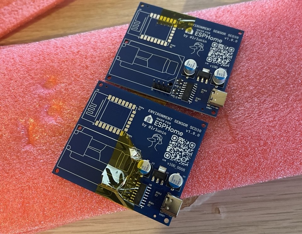
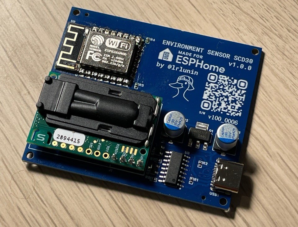
Then, with my not very steady hands, the sensor and the ESP8266 board were soldered.
Firmware
When using Home Assistant (HASS), there are no particular nuances. The sensor integrates into the smart home with one click.
The initial goal was to develop a device that could work independently. I do not consider it advisable to set up HASS for a single device. I also did not want to reinvent the wheel, but to use ESPhome as a basis.
Among the ready-made components for ESPhome, there is a web_server that raises a simple web interface with sensors and firmware update capability on the controller itself.
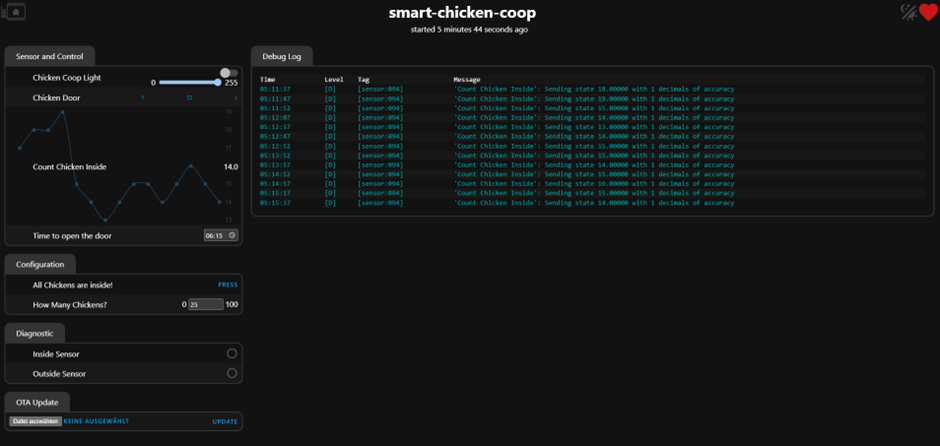
During the firmware configuration process, however, it turned out that the latest sensor values are stored on the client side and are lost after the page is refreshed, so the graph is built from scratch.
For this, I had to write my own small component history_container, which subscribes to sensor updates and remembers the last N values and the time difference between measurements.
The frontend was also slightly modified to support the container and, in the meantime, the CSS selector that did not work in Safari and Firefox was fixed.
I was pleasantly surprised by the ability to store all the necessary resources for the site directly on the ESP, so the sensor becomes a completely self-sufficient device.
Controller Calibration
During the testing of the devices, I noticed that the temperature of the SCD30 differs significantly from my old SHT31-D sensor in a larger direction, so calibration is needed.
The reliability of the old sensor values was also supported by the built-in temperature sensor in the MH-Z19, which showed similar values, and common sense.
For this, I left both sensors connected to HASS for several hours with the window closed. Then I unloaded both sets of values and simply calculated the constant that minimizes the root mean square deviation between the two sets.
Calibration code
import pandas as pd
import numpy as np

# csv file exported from Home Assistant
df = pd.read_csv("history-0010.csv")

# selecting reference and sensor for calibration
true_values = df.loc[(df['entity_id'] == 'sensor.bedroom_sensor_bedroom_temperature')].drop(columns=['entity_id'])
to_calibrate = df.loc[(df['entity_id'] == 'sensor.scd30_0010_scd30_temperature')].drop(columns=['entity_id'])

# for some reason the values were not parsed as numbers
true_values['state'] = true_values['state'].astype(float)
to_calibrate['state'] = to_calibrate['state'].astype(float)

# converting strings to date
true_values['last_changed'] = pd.to_datetime(true_values['last_changed'])
to_calibrate['last_changed'] = pd.to_datetime(to_calibrate['last_changed'])

# assigning date as index
true_values = true_values.set_index('last_changed')
to_calibrate = to_calibrate.set_index('last_changed')

# sorting both series
true_values = true_values.sort_values('last_changed')
to_calibrate = to_calibrate.sort_values('last_changed')

# bringing both series to a common time scale
df_merged = pd.merge_asof(true_values, to_calibrate, on='last_changed', direction='nearest', suffixes=('_true', '_calib'))
# calculating root mean square error
def calculate_rmse(offset):
    diff = (df_merged['state_true'] - (df_merged['state_calib'] + offset)) ** 2
    rmse = np.sqrt(diff.mean())
    return rmse

# range for offset search
offset_range = np.linspace(-10, 0, 1000)

rmse_values = [calculate_rmse(offset) for offset in offset_range]

best_offset = offset_range[np.argmin(rmse_values)]

print(f"The optimal offset that minimizes RMSE is: {best_offset:.2f}")
We get the following graph for the reference sensor and the new sensor before and after calibration
The sensor itself supports setting a temperature offset, which is also taken into account for calculating relative humidity. I was very surprised that the offset value is applied with a time delay, even if the device is turned off and on.
I could understand if the offset change directly during the operation of the device was accompanied by a time delay. This would mean the presence of a buffer of the latest temperature values to reduce noise. The delay would be due to replacing the values in the buffer with new values with an offset (and even then, the correction could be applied after calculating the average buffer value).
If there is a delay and power outages, this suggests that the buffer of the last values is in non-volatile memory. Perhaps the developers wanted to reduce noise for the first temperature measurements after switching on, assuming that the temperature before and after switching on did not change so much.
Conclusion
I am more than satisfied with the final result. The accuracy of the measurement and the ability to customize, the complete openness of the project, and the ease of use of the software (EasyEDA and Autodesk Fusion) pleasantly surprised me.
The total cost of one unit was $24, calculation: $76.77 / 10 (boards with components) + $1.43 (ESP8266) + $14.89 (SCD30) and is a fully customizable and easy-to-use device.
Links
SCD30 on AliExpress (https://de.aliexpress.com/item/1005007654300194.html)
ESP8266 on AliExpress (https://de.aliexpress.com/item/1005007014587323.html)
Link to the GitHub repository with all files and project description https://github.com/lrlunin/scd30-esphome
Link to the EasyEDA project https://oshwlab.com/lunin.leonid/scd_with_pins_uart


Write comment