
- Network
- A
How we implemented QoS InfiniBand for prioritizing ML training from a network perspective
In this article, we’ll discuss how the Yandex Infrastructure team implemented QoS in InfiniBand networks with limited vendor support and scarce practical documentation. We’ll talk about the motivation: the growth of mixed workloads in the internal cloud and the need for predictable SLOs for different trainings. We will also explore how QoS and the DragonFly+ network topology can be interconnected.
Hello! My name is Roman, and at Yandex Infrastructure I work in the Network Operations Center (NOC) team, focusing on data center network fabrics. This includes networks of our internal cloud that connect our GPUs, where ML engineers run numerous trainings of various models. Considering the explosive growth of ML recently, it’s important to note that the mixed load on the internal cloud is constantly increasing, but we still want to ensure predictable SLOs for internal users.
We don’t often talk about the networks connecting our GPU servers. In this post, I will discuss InfiniBand technology and the concept of Quality of Service, which has been implemented in it despite limited vendor support. I will go over the QoS configuration and the test setup of an InfiniBand GPU cluster, as well as show how we implemented traffic prioritization for different trainings in the cluster. Let’s go!
What InfiniBand QoS Is
One of the features of InfiniBand networks, which fundamentally distinguishes them from TCP/IP networks, is the centralized Control Plane. In an InfiniBand fabric, everything is managed by a controller — the Subnet Manager; in our case, this is OpenSM. Without going into too much detail (there’s a lot to write about this), I’ll highlight its most important functions:
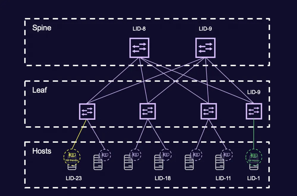
The controller manages addressing in the fabric, assigning a Local ID (LID) to all nodes for switching purposes.
The controller programs the forwarding tables of switches (Linear Forwarding Table — LFT).
…and even the Quality of Service policies, which I want to talk about today, are also managed by the controller.
A bit more detail about what InfiniBand is and what’s under the hood can be found in the talk from our networking technology conference nexthop 2022.
Since this article is aimed at a broad audience, I’ll add some context: what exactly is Quality of Service, and what service quality are we talking about? Here, it’s important to keep a few points in mind:
QoS allows setting different priorities for different types of traffic.
In InfiniBand, QoS is implemented using Service Level (SL) and Virtual Lanes (VL).
VL is a mechanism for creating virtual links within a single physical link. Essentially, it is very similar to "queues" on a switch port in TCP/IP networks.
SL is a field in the Local Routing Header (LRH) that defines the service class of the packet. Here, we can also find an analogy in TCP/IP networks: the DSCP field in the L3 header, for example, which sets the packet priority.
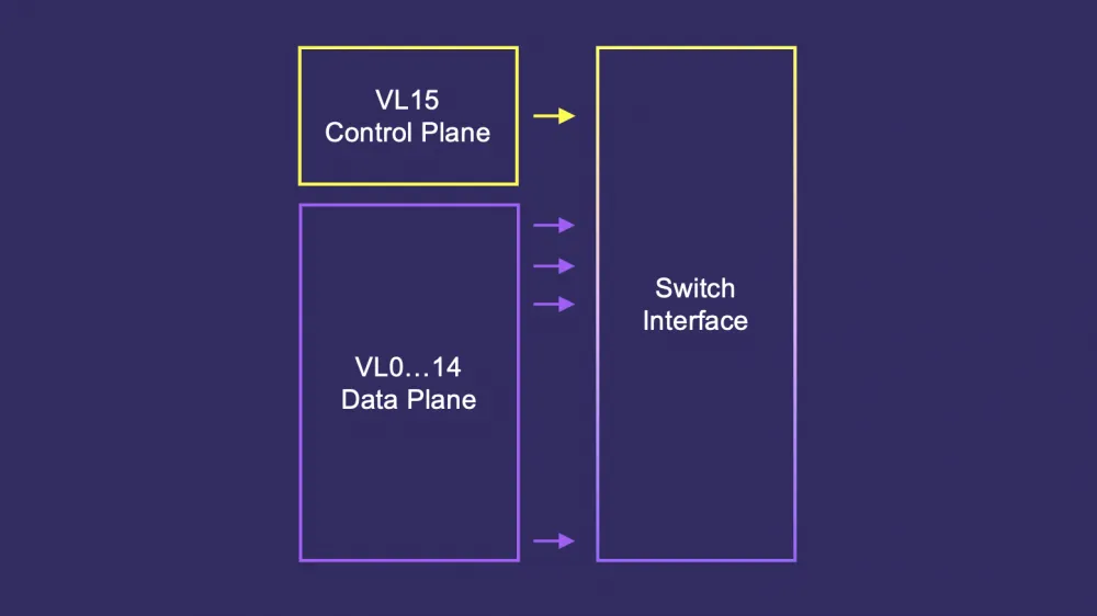
In modern IP switches, typically 8 queues are implemented per interface. The InfiniBand specification defines 16 VLs: fifteen for the Data Plane and one for the Control Plane. But when we talk about the current InfiniBand implementation, the hardware also implements eight lanes. As in IP switches, InfiniBand has a dedicated queue for control-plane traffic. In InfiniBand, this is VL15; in Ethernet, there can be several such special queues — 6 and 7.
The principle is very simple: different VLs can have high or low priority and different weights, defined by the number of 64-bit units, from 0 to 255. We can "color" packets differently (SL) and "map" them in a specific way to a VL with a given priority and weight:
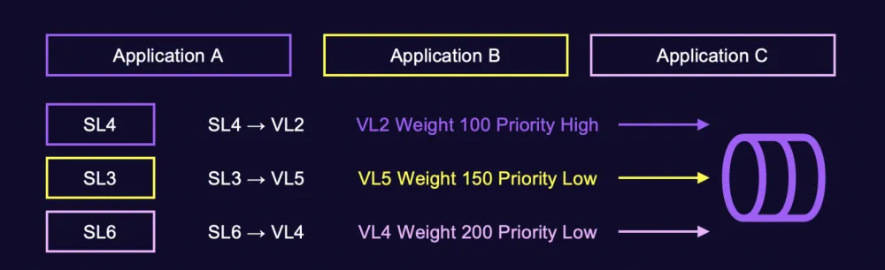
I saw this image once during an InfiniBand networking training by Mellanox in 2020. At that moment, it seemed very simple and clear to me.
A packet arrives, and it has a Local Routing Header (LRH).
We look at the Destination LID to determine which port to send the packet to next.
If QoS is configured, we also consider the SL-to-VL mapping and map it to a specific virtual lane.
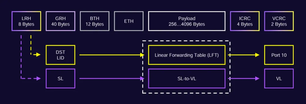
In reality, as often happens, it turned out to be somewhat more complicated.
When the story of QoS in our InfiniBand network started moving from slides in presentations to practical application, I decided to refer to the original source — the InfiniBand specification. To my surprise, I found that the LRH header contains not only the SL field, which we were taught about in the course, but also a VL field, about which nothing was explained for some reason. Such life the Mellanox InfiniBand networking training had not prepared me for.

Here is what the InfiniBand specification says about all this: I will provide a few points that seem most important to me.
The SL field must not change when a packet passes through the subnet.
The VL field may change when a packet passes through the subnet.
SL to VL mapping is used to change virtual lanes (VL) when a packet passes through the subnet.
Switches must have an SL2VL mapping table that maps the SL, input port, and output port of a packet to the virtual lane VL that will be used on the next hop.
The last statement is particularly important because it effectively means that changing the VL is allowed not only based on the packet’s SL label, but also depending on where the packet comes from and where it is going. Thus, the SL2VL mapping mechanism can be part of the Control Plane when making routing decisions (we will return to this point later). With this, we consider the introductory part on theory complete. Very interesting, but why do we need all this?
What problem do you want to solve with QoS? (c)
Although this subtitle is our local meme inside the NOC, it is very important to answer this question correctly. To add context, I will show how the InfiniBand network, which connects our GPUs, is structured.
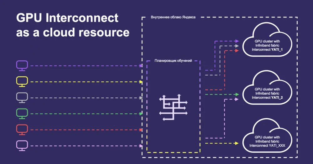
In general, a group of servers with GPUs, connected by a separate InfiniBand (or RoCEv2) interconnect network, is called a cluster with the mysterious abbreviation YATI-{NUM}. We have quite a few such clusters. They can be of different sizes, the GPUs in them may be of different generations, and the network can be built in different topologies and with different generations of equipment.
The one thing that remains unchanged in all these clusters is this: each such cluster is a cloud resource on which models from different users can be trained. At any given time, dozens (or even more—depending on the size of the cluster and the number of trainings) operations can be running on the cluster. And for all these operations, the InfiniBand cluster network will represent a shared resource, for which they can compete with each other. It is logical to assume that some trainings are more important and have higher priority, and we need to ensure the translation of these priorities in terms of network guarantees.
For a long time, all these thoughts simply lived within us: it was intuitively clear that it would be good to address this, but we didn’t have a clear answer to the question of what exactly should be improved. Everything changed when, at one of the GPU infrastructure and NOC syncs, colleagues showed us the image below.
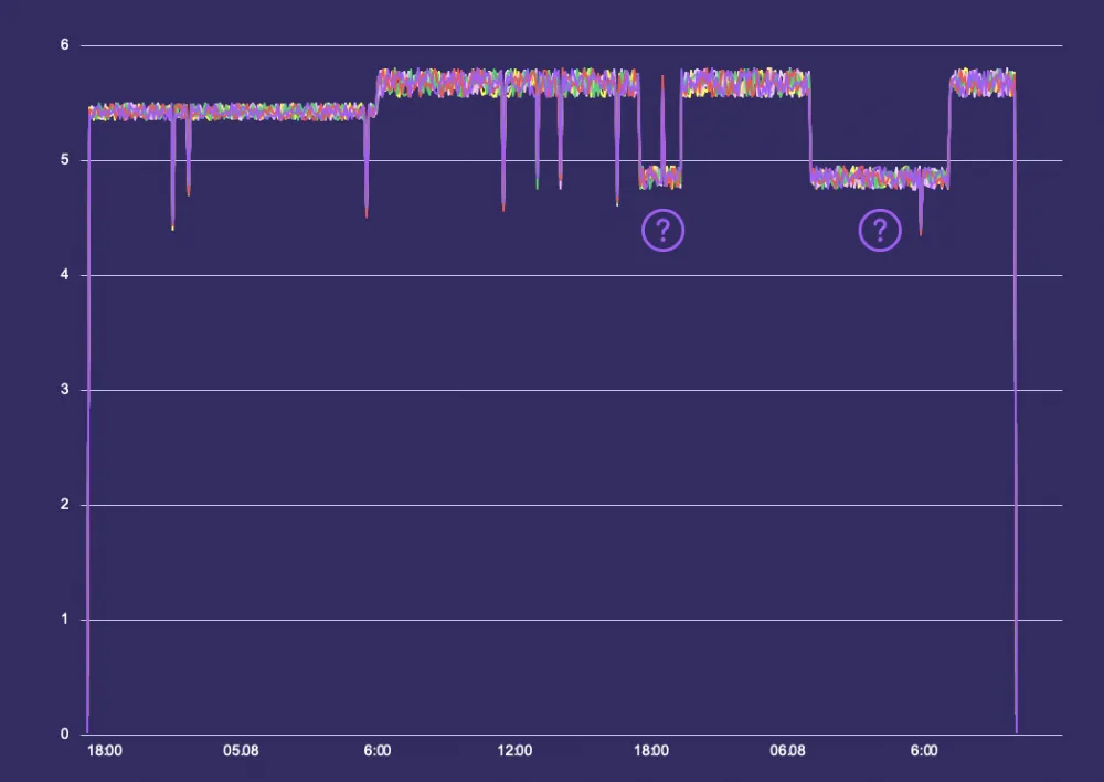
Here is a network utilization graph for one large training session. The dips in this graph suspiciously correlate with the starts of another training on the same cluster.
At this moment, we had an answer to the question from the subtitle: we want to learn how to assign priority to an operation from the network's point of view.
How to understand that it works?
As we have already figured out, all QoS policies in the InfiniBand fabric are controlled by the controller. I won’t provide configuration files in this post (if anyone is interested, you can watch the video from nexthop 2025, where we talked about this) — I will only describe the basic hypothesis that needed to be tested. We wanted to make sure that the scenario of prioritizing one type of traffic over another works in principle. The hypothesis was as follows:
We have two types of traffic, "colored" accordingly in SL0 and SL1.
We consider SL1 to be of higher priority and allocate 80% of the port's capacity to it.
SL0 is used for less priority traffic and is allocated the remaining 20%.
In this case, we observed a significant difference: the benchmark "colored" in SL1 significantly outperformed the benchmark "colored" in SL0 — just as intended. After that, we conducted several more tests confirming that this behavior was not accidental. At this point, we gained the ability to prioritize traffic in the InfiniBand fabric.
Network Topology and QoS
It would seem that this is all: the tests are done, the result is obtained, we can move on to implementation and call it a day. But no. In the previous paragraph, I deliberately emphasized the topology in which we conducted the tests — FatTree. The settings we tested were valid specifically for it. But what happens if the network topology changes, for example, to DragonFly+?
We discussed this topology, though in the context of TCP/IP networks, at nexthop 2024
If we were talking about a conventional TCP/IP network, I would confidently say that nothing would change. QoS queue settings are not related to the network topology; they are local to each switch and do not participate in the network's Control Plane. In other words, the network topology can be absolutely anything, and this would not require reinventing the necessary QoS configuration.
— Is this statement valid for an InfiniBand network?
— No.
At the beginning of the post, I presented the format of the Local Routing Header (LRH), which is used for forwarding in the InfiniBand fabric, along with excerpts from the specification regarding its SL and VL fields. This was, again, intentional. The specification implies the use of SL2VL for the network Control Plane when making decisions about which path a packet will follow. But let's go step by step: first, let's look at the DragonFly+ topology.
DragonFly+
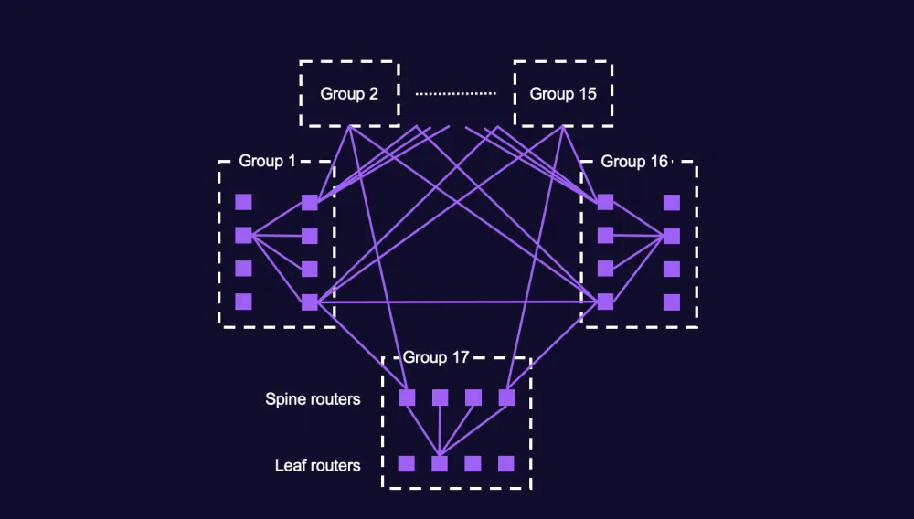
DragonFly+ (abbreviated DF+, also known as Megafly) is a fully connected full-mesh topology consisting of groups of nodes. Each group, in turn, represents the already familiar Leaf-Spine FatTree topology (in the context of DF+, the term Clos topology is often used).
Looking at this topology, it's quite easy to conclude that from one group, for example, Group 1, you can reach another group, say Group 17, in several different ways. The first and most obvious way is to take the direct link connecting Groups 1 and 17. But what if this link has limited capacity (and it does), and all the traffic between the given groups doesn't fit into it? Then, we can go through a +1 hop path, for example, via Group 15, and thus gain additional capacity between the groups. This principle—gaining extra capacity via a transit group—is the basis of the entire routing principle in the DF+ topology. Besides the described +1 hop routing, a +3 hop option is also possible, where in the transit group we descend from the Spine level to the Leaf and then rise again to the Spine level.
Why all this complexity? How is it better than the straightforward and convenient FatTree topology? The answer is very simple: DF+ allows building a network without an additional layer of Super-Spine switches (or second-level Spine, as you prefer), which in turn leads to direct cost savings. This motivation is the basis of why we have InfiniBand clusters built on the DF+ topology.
Infiniband QoS in DF+
So how are QoS policies and the DF+ topology related in an InfiniBand network? As shocking as it may sound, in the most direct way. The fact is, in an InfiniBand network, depending on the path a packet takes—whether it’s direct, +1 hop, or +3 hops—it will be processed in different VLs.
If the packet goes via the direct path, nothing changes. But if the packet goes via a +1 or +3 hop path, then at the point in the network where the packet starts to “rise” up the topology for the second time, a VL remapping occurs. This is described in the specification regarding the VL field, which can change when the packet passes through the fabric. In the example in the image below, these are VL0 and VL1.
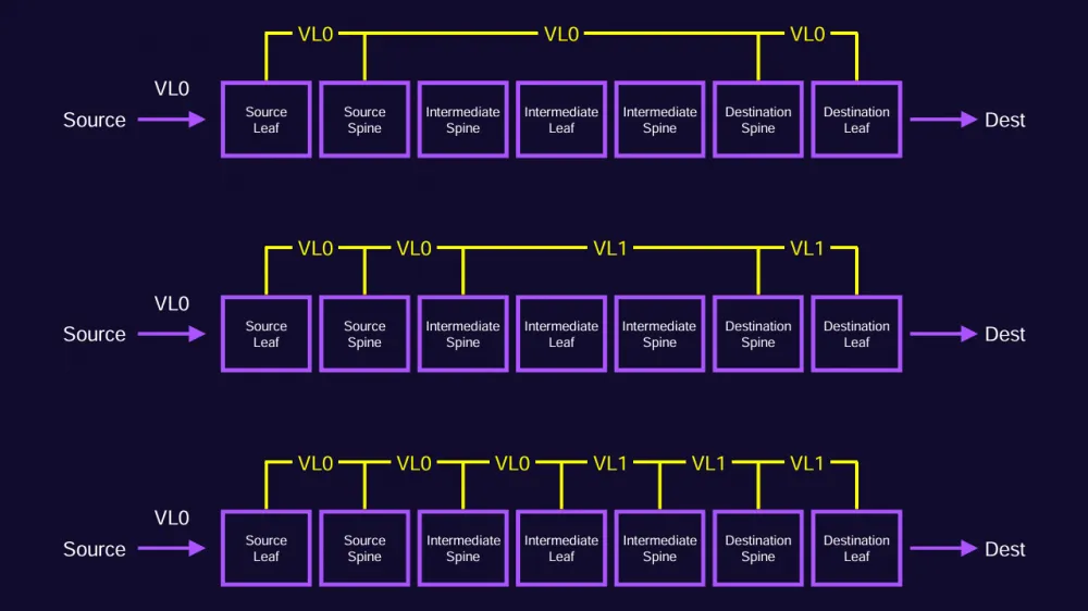
But why is this remapping necessary? To answer this question, we need to remember the fundamental principle of InfiniBand networks: it operates with Credit Based Flow Control, which, in turn, ensures lossless data transmission. For an InfiniBand port to start packet transmission, it must first receive credits from the peer port, which guarantees that the receiving port will be able to accept our packet and forward it. It is important to note here that different VLs will have their own credits, with a separate dedicated buffer.
This mechanism creates a fundamental problem known as the "credit loop deadlock," where cyclic dependencies between buffers of different ports can cause the ports to stop issuing credits to each other in a circle, and data transmission in the InfiniBand network will come to a complete halt at that point. This problem is solved differently in different topologies. For instance, in FatTree routing algorithms (in InfiniBand terminology, this is typically referred to as a routing engine; the main ones are ftree, updn), this problem is addressed by limiting the paths that lead to cyclic buffer dependencies. For example, when a packet passes through a FatTree topology, it can only rise from the Leaf level to the Spine level once; if the packet has descended from the Spine switch to the Leaf, it cannot rise back to the Spine level — such a path will be considered invalid. But applying this solution to the DF+ topology is not possible, as the whole point of this topology is to gain additional capacity between groups through transit, which requires the ability to "descend" down the fabric and rise back up.
As you may have already guessed, the VL remapping mechanism solves the "credit loop deadlock" problem in this case: essentially, we break one continuous buffer into two independent ones. This, in turn, breaks the cyclic dependency and prevents deadlock.
What does this VL remapping change for DF+ in relation to our original task? Actually, quite a lot.
Let's start with the fact that the routing engine for the DF+ topology (dfp, dfp2) requires two VLs for processing a single class of traffic: one VL for direct traffic, and the second for traffic via the +1 or +3 hop path. This means we cannot use a one-to-one mapping of SL <→ VL; we need to map each SL to 2 VLs. This clearly leads to a reduction in the number of available "SL-colors" in the factory by half. SL2VL no longer needs to be configured in the configuration file, as the SL2VL mapping becomes part of the Control Plane, and it is now directly managed by the routing engine (dfp/dfp2).
The drama of the story is added by the fact that the official InfiniBand documentation from NVIDIA (formerly Mellanox) does not disclose this entire story and mostly contains descriptions of the most primitive scenarios for working with the SM, related to its basic startup scenario. The most useful sources of information were community posts and articles for the professional community. After diving deeply into them, we eventually obtained the QoS config for our clusters built on the DF+ topology. Finally, we can move on to the implementation!
InfiniBand QoS as a product
After testing the hypothesis about the possibility of traffic prioritization, the question arose of how to integrate this into existing training processes. But first, we needed to come up with the business logic.
There were different hypotheses about how this could be done. One of them was the hypothesis of assigning a separate "color" to each project (or one "color" to a group of projects). But it left a lot of blanks: starting with how to distribute the weights of SLs for different projects, and ending with the technical implementation. The number of "colors" we can use is much smaller than the number of our projects. The logic of mapping projects to different "colors" also looks extremely unclear.
As a result, we settled on the most understandable and simple option. In the final implementation, we decided to keep our test config with SL0 weighing 20% and SL1 weighing 80%. We consider BIG training to be a priority, meaning training that involves a number of GPUs in the cluster exceeding a certain threshold. We tried to make the logic of this threshold flexible. We have a fairly large number of clusters of different generations and sizes in operation, so having one business logic that combines them all would be quite inconvenient. Therefore, we decided that the threshold should be a configurable parameter for each cluster separately. This threshold can be set either as a percentage of the total number of GPU hosts in the cluster, or as an absolute value.
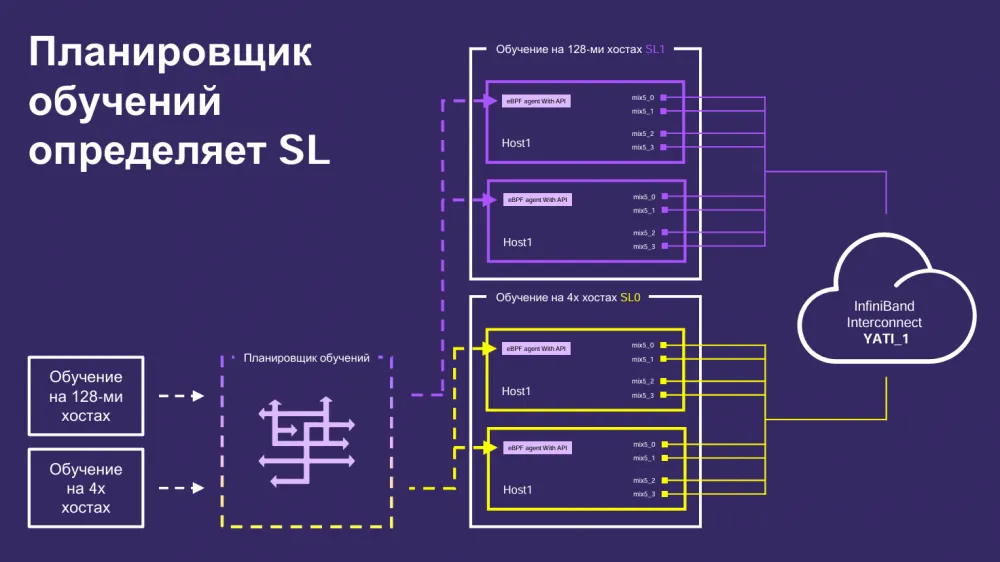
The training scheduler determines the SL of the training during its allocation. It then passes this information to the agent on the host, which colors the traffic in the specified SL when the training is running. It’s important to note that the agent on the host will always recolor the training traffic. If the training is priority — in SL1, if not — in SL0. If the user brings their own “paint” in their code (and this can be done), the traffic will still be recolored. There is no trust here 😎
What’s next?
In fact, this entire story may also be useful to us in another project. Under certain conditions, a situation may arise where we have projects with training and projects with multi-host inference coexisting in the same cluster, which will also consume network resources. In this case, it seems logical to also separate these two different types of traffic into different “paints.” The priority in this case would logically be given to inference, as it is, by its nature, real-time traffic.
I hope the article was useful! I will be happy to answer questions here in the comments or in our community Yandex Infrastructure — drop by our TG to learn more about how we build Yandex’s internal infrastructure.



Write comment