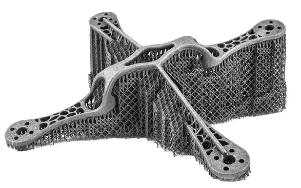
- Software
- A
For 30 years we implemented Ansys in Russia. Then it left — we had to sit down and write our own CAE for additive printing
In short, this is software that simulates what will happen to a titanium blade while it is being printed by an SLM printer. And why until 2022 this task in Russian aircraft manufacturing was solved using Ansys Additive, and now it has to be solved with something else
In short, this is about software that simulates what will happen to a titanium blade while it is being printed by an SLM printer. And why, until 2022, this task in Russian aircraft manufacturing was solved using Ansys Additive (less often — Simufact Additive), and now it has to be solved with something else.
We have been digging into this 'something else' for the last few years. Below is about the current state of affairs: what works, what we still cannot do, and why metal 3D printing in aviation is, to put it mildly, not 'press a button — get a part'.
What is printed in aviation and why
When people talk about additive technologies in aircraft manufacturing, they usually mean two categories of parts: either beautiful renders of 'topologically optimized' brackets, or real parts — guide vane blades, fuel nozzles, heat exchangers of complex shape, structural frame elements. The technology is the same — selective laser melting of metal powder (SLM, Selective Laser Melting): the laser fuses the required areas of a thin layer of powder, the build plate lowers, the next layer of powder is spread, and this goes on for dozens of hours in a row.
Why is this used in aviation:
geometries that cannot be obtained by casting or milling — internal channels, thin walls, variable cross-sections;
weight reduction by replacing an assembly with a single part and through topological optimization;
restoration of expensive parts (cladding wear zones of blades);
reducing the number of components in an assembly — where there used to be twenty bolted brackets, there is now one single part.
This sounds like a conference presentation. The presentation ends when you first run a large titanium part on a printer with a build volume of around 400×400×400, and the output is a piece of metal that is slightly warped, and in one place the build plate was torn off the base plate — together with a piece of the base plate itself.
Why simply 'printing' does not work
Inside the printer, essentially, repeated local welding takes place: the laser melts powder, the metal solidifies, the next layer heats the previous one, and so on. Each layer is a thermal cycle, in which the following accumulate:
Residual stresses. Invisible, but grow as the part is built up.
Deformations. The part distorts relative to the CAD model — by tenths of a millimeter in some places, by whole millimeters in others.
Microcracks. Both hot (during crystallization) and cold (during subsequent heating-cooling cycles).
Separation from the build plate and supports. When stresses exceed what the supports can withstand, the print may stop, or the part may tear off along with a chunk of the build plate.
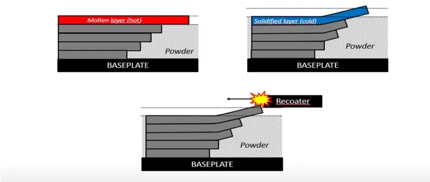
In aviation, this is where trouble starts. A blade with ~8% plastic deformation in the upper airfoil zone may pass geometry checks — and at the same time develop a microcrack far earlier than its design service life due to reduced long-term strength. A bracket with an unexpected residual stress distribution will respond to vibration differently than expected.
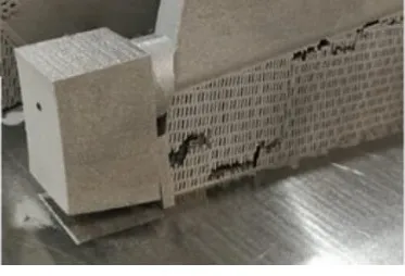
Tuning parameters via trial and error is expensive. One run of VT6 titanium powder for a large part often costs a six-figure sum just for the material alone, plus dozens of hours of printer time, plus operator labor. Testing five to seven combinations of power, scanning speed, and part orientation — and the budget for "trial runs" runs into the millions.
Where CAE fits in
The idea is simple: instead of running a real test, simulate the process numerically. Calculate heating, cooling, stress and strain accumulation layer by layer. The output includes a strain field across the part, a map of residual stresses, a forecast of potential crack formation zones, and an assessment of where supports will break off.
Several vendors have been developing this field globally. In the Russian aerospace sector (and across the post-Soviet space overall), two solutions have historically stood out:
Ansys Additive Print / Additive Suite — the primary tool used by customers that were the first to adopt SLM.
Simufact Additive (now under the Hexagon brand) — with its strong focus on accounting for metallurgical transformations.
There was also Autodesk Netfabb Simulation and a couple of smaller solutions. Since 2022, all of this has, in short, stopped being an option for Russian enterprises. Licenses are not renewed, there is no support, no updates. Those who managed to set up their process on Ansys Additive before that are either preserving what they have, or looking for a replacement.
We have been implementing CAE systems in Russia and the CIS for over 30 years — including as an official Ansys integrator (under the CAE Expert brand). So when the vendor left, we had a choice: switch to something completely outside our core expertise, or try to build our own solution. We chose the latter.
What we ended up with is SIMMAX‑ADDITIVE
SIMMAX is a family of three proprietary modules:
SIMMAX‑THERMAL — calculation of heat treatment processes and mechanical properties after thermal exposure.
SIMMAX‑WELDING — welding simulation taking into account metallurgical transformations and residual welding distortions.
SIMMAX‑ADDITIVE — simulation of SLM printing processes.
All three modules are included in the Unified Register of Russian Software. The entry for SIMMAX‑ADDITIVE is No. 31 105 dated 10.12.2025.
What the module does at the current stage:
accepts CAD geometry in STL format, process parameters (power, scan speed, layer thickness, part orientation), material properties across a wide temperature range, and support configurations;
it has a built-in automatic mesh generator inside; supports can be imported from CAD or generated directly within the system;
it solves the thermomechanical problem layer by layer: temperature distribution, stress accumulation, deformations, and plastic zones;
the output provides deformation fields along all axes, residual stress maps, yield strength profiles under steady-state thermal cycling, and an assessment of probable crack formation zones — in the part itself, the substrate, and the supports.
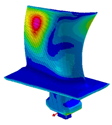
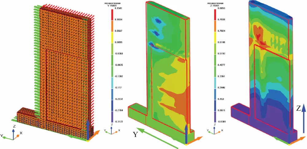
On the reference quarter of a turbine blade, we get a result that qualitatively matches what Ansys Additive produces for this class of tasks: compression zones in the lower part of the blade, accumulated plastic deformations of up to ~8% in the upper zone, a forecast of warping along the Y and Z axes that can potentially be used for pre-compensation in the printer software.
Now, let's talk about honesty
I don't have any stories along the lines of "we implemented SIMMAX‑ADDITIVE at twelve aviation enterprises, saving 200 million a year". Not because I don't want to write them. But because they don't exist yet.
The registry entry is fresh, dated December 2025. We have not yet completed any production projects for large aerospace customers using SLM. What we have right now is in-house validation on reference geometries, testing on classic tasks from open literature, and algorithm testing on "model" parts.
This is where the classic problem of niche engineering software in Russia arises: for a product to "mature", real use cases are needed. For real use cases to appear, someone has to be willing to launch a young product on a production task where the cost of an error is measured in millions. It is easier to take this step with Ansys Additive, which has 20 years of accumulated validation database. It is harder with a fresh Russian CAE solution. But without this step, no "Russian analog" will ever appear in principle.
Dear engineer readers, if you work with SLM in aviation or related industries (implants, tooling production, power components for ground equipment) — I am interested in your expert feedback in the comments. First and foremost, two things:
Which tasks in your practice were handled well by Ansys Additive, and which were handled poorly? Where did you have to "work around" the product's capabilities using external scripts or expert intuition?
What would be critical for you to see first in a Russian solution — accuracy in terms of warpage, processing speed for large parts, correct handling of exotic alloys, a convenient interface for defining supports, or something else?
The debate of "Russian software vs. Western software" is usually conducted on a political level. I find it far more interesting when it takes place on the level of physics and validation: what support models are used, what their limitations are, what tasks we can actually solve, and which ones we cannot yet.
If this topic gains traction, in my next materials I will write in more detail about the thermomechanical formulation for SLM and explain why the "correct" support model in the problem turns out to be almost more important than the model of the melting process itself.

Write comment