- DIY
- A
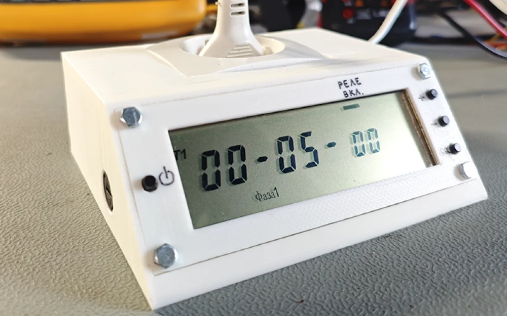
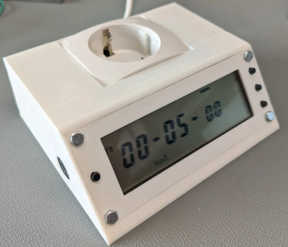
Programmable socket on AVR
The article describes the development of a compact socket with programmable on/off cycles for load control. The device is based on the Atmega48PA microcontroller with LCD display indication and powered by a transformerless power supply. It is suitable for photorezist exposure, lighting control, and other household tasks. The article provides circuits, PCB layouts, STL files for the case, and firmware.
The device is a socket with a time setting for the on and off state of the load and the number of repetitions of this cycle. It was created for the exposure of the photoresist to ultraviolet light, as well as for additional exposure of products printed on a photopolymer printer. The internal solid-state relay is rated for up to 2A, allowing this socket to be widely used in households, for example, for the automatic activation of a phytolamp for plants.
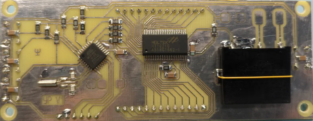
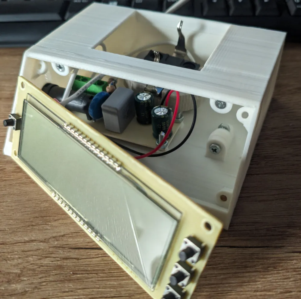
The device consists of two boards: a control board and a board for the transformerless power supply (BIP).
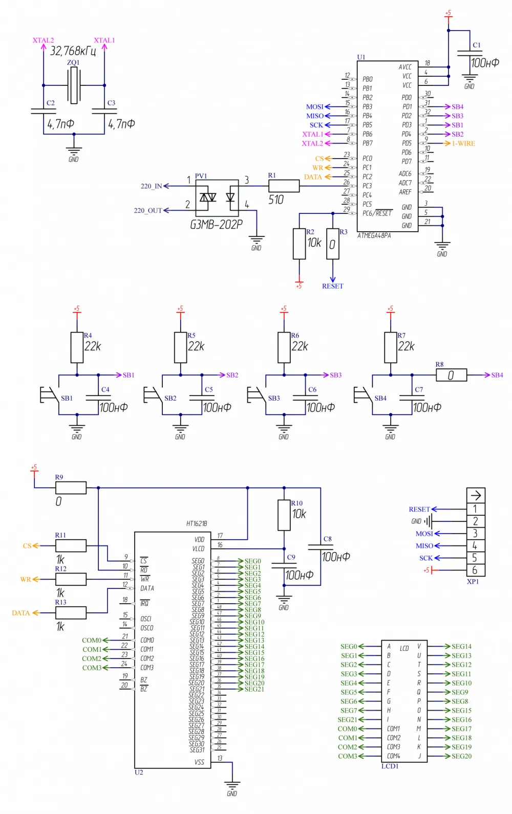
The control board is based on the Atmega48PA microcontroller, which controls the LCD display via the HT1621B driver (display from the Mercury 230 counter). The board is powered by 5V from the BIP board. Four buttons are used to set the socket's operating time and to start the algorithm. Capacitors on the buttons are installed to suppress bouncing hardware-wise.
The algorithm configuration involves setting the time (from 1 second to 99 hours) for two intervals, configuring the relay position (on-off) for each interval, and the number of repetitions of these intervals (up to 99).
The load is switched by the G3MB-202P solid-state relay (~230V, 2A). Time measurement is done by the ZQ1 quartz clock, which usually requires adding capacitors C2 and C3 in the circuit, but for this specific quartz, the capacitors had to be removed because their presence significantly reduced the frequency and caused incorrect time counting. The XP1 connector is used for programming the microcontroller and is later desoldered from the board. The board also has pins for connecting the DS18B20 temperature sensor via the 1-WIRE interface to monitor the temperature of the solid-state relay (not installed in the current version of the board). Monitoring the temperature of the solid-state relay is important because the switched current decreases significantly as the temperature rises.
Zero-ohm resistors on the schematic are jumpers that simplify the board layout.
The firmware for the microcontroller is written in CodeVisionAVR and is available in the archive at the end of the article.

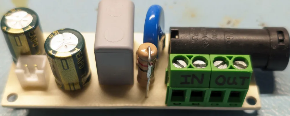
The BIP board is based on the classic design and is rated for a 5V output voltage and a maximum current of 30mA. A fuse is installed directly on the board, as no other external fuse mounting was available. The Altium Designer project (link at the end of the article) also includes a version of the board without the built-in fuse.
WARNING! The BIP does not provide galvanic isolation from the network. All circuits on the control board are exposed to potentially dangerous voltages. All work with the device (including programming) must be done strictly with the power off or through an isolated power source.
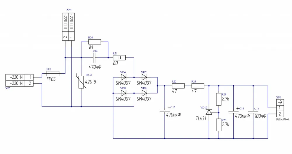
The network voltage is supplied to the XP5 connector, while the relay on the control board and the socket are powered from the XP4 connector. The board features a varistor to limit potential voltage surges in the network. Resistor R20 is used to discharge capacitor C14 after the board's voltage is removed. Resistor R21 is used to limit the inrush current to the board when the voltage is applied. The circuit before resistor R22 essentially works as a current source and is calculated using the following formula:

f – network frequency (50Hz),
C – capacitance of capacitor (C14),
Uin – input voltage (230V),
Uout – output voltage (5V).
Next, this current passes through resistors R22, R23 (their optimal resistance is about 100 Ohms) and splits between the TL431 zener diode and the load. If no load is connected, all the current will flow through the TL431, so this circuit is limited to 100mA. To increase the output current, a more powerful regulator is needed. Capacitor C14 should be an X2 type rated for 275V for safety in case the capacitor fails.
The output voltage is set by resistors R24 and R25, which are calculated based on the TL431 control contact voltage of 2.5V. In this case, for 5V output, the resistors have the same value. R25 is selected as 2.7kΩ to ensure a current of around 1mA flows through the control contact of TL431.

The device casing is 3D printed and turned out to be not very optimal – there is a lot of free space inside.
In the future, a temperature sensor for the relay and an LED to indicate the relay’s on state will need to be added to this circuit, as currently, the relay's position is displayed by a line on the display, which is not very intuitive.
In the end, the device proves to be an excellent tool when it's necessary to cyclically switch the network voltage at specified time intervals.
For those who want to replicate this device, I have uploaded an archive with all the necessary sources:
https://disk.yandex.ru/d/8wqBpl_UGNBONw
The archive contains the Altium Designer project, CodeVisionAVR project, and STL models of the casing.


Write comment