- DIY
- A
Designing a motor controller with GitHub Copilot
There is always a place in a smart home where motorized systems can be applied. These include adjustable desks, automatic doors, windows, electronic locks, stair lifts, gates, garage doors, blinds, awnings, antenna positioners, solar panel rotators, and so on.
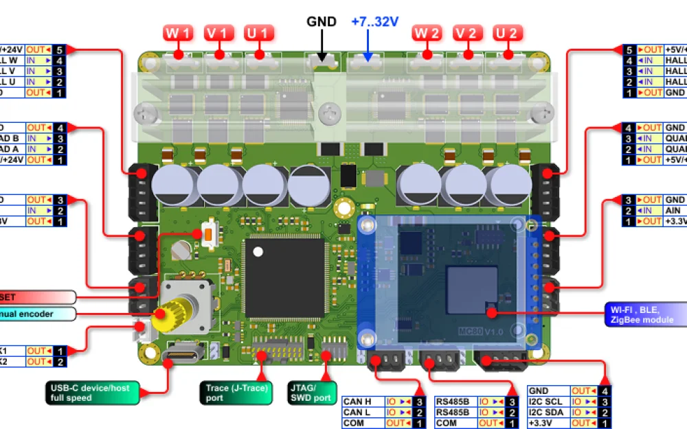
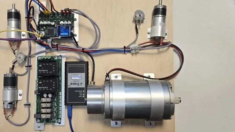
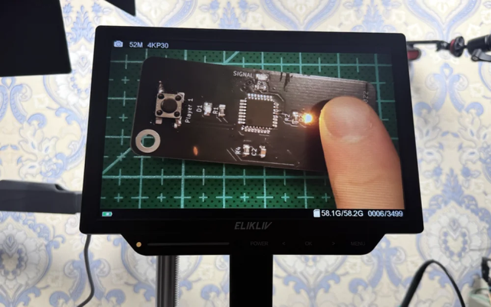
Here is a controller design for four DC motors, created mostly using code generation with GitHub Copilot in VS Code. The hardware foundation is the MC80 universal motor controller board.
The board can run each motor forward and backward at a variable speed according to a given acceleration and deceleration law, without jerks or stuttering (which is important for conveyor lines, lifting mechanisms, and so on). In this project, the control can be local, manual, via PC, or remote through a CAN bus. But the board's capabilities do not end there.
The board's performance is sufficient to provide modulation frequencies up to 32 kHz for all motors simultaneously, while running speed control algorithms and network interactions.
In the parameters, three profiles for acceleration and braking can be set individually for each motor.
The S-curve profile ensures smooth operation, while the linear profile provides lower current spikes. The dangers of controlling DC motors were covered in this article.
How the board was developed is described here.
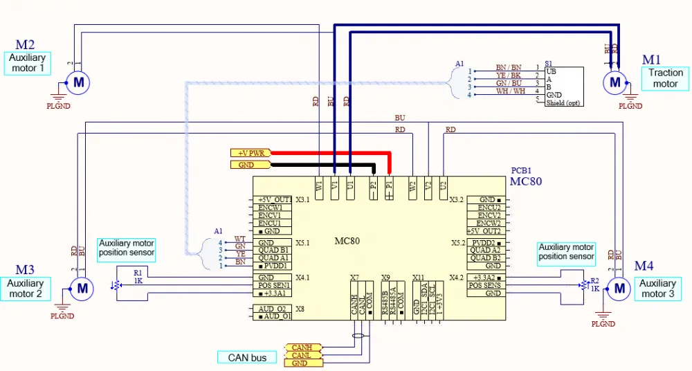
Electrical Diagram
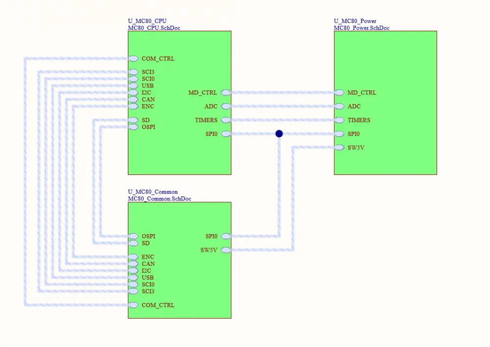
Below is the board schematic. It is created in a hierarchical style because it contains two identical motor driver subsystems. This saved time. However, in Altium, once you decide to make a hierarchy, the entire schematic must be hierarchical.
However, it was done in the traditional way, without using AI.
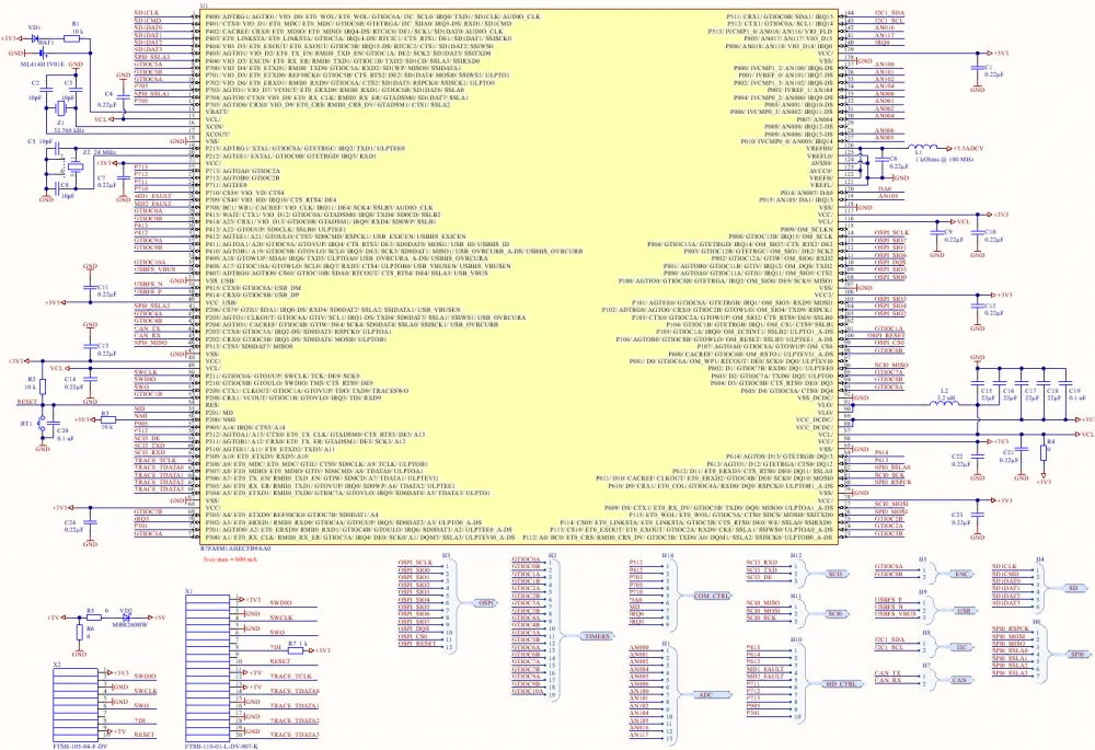
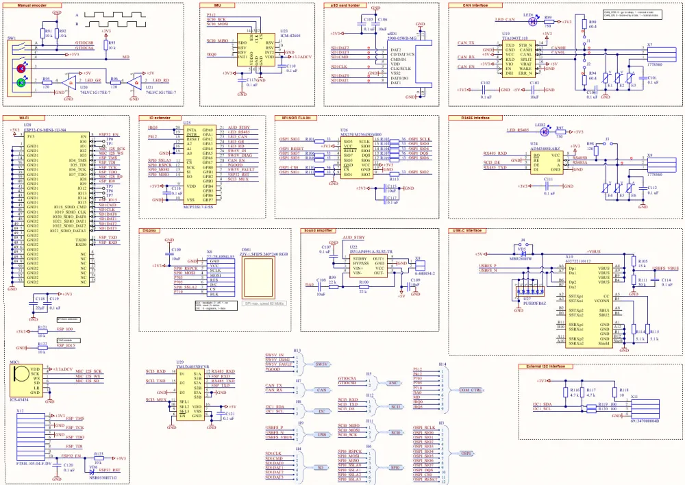
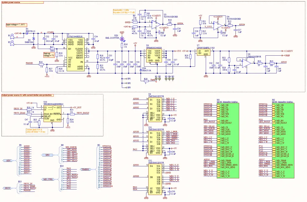
The board has many interfaces, but I didn’t want to make the new microcontroller in BGA, nor did I want to use the largest TQFP. So, I had to use input-output expanders and analog multiplexers. A keen observer might even notice that the ESP32 and SD card share a single SDIO interface.
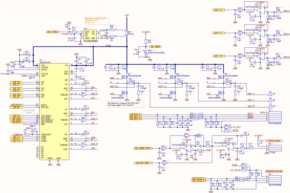
The motor driver scheme is universal and can be applied to both DC motors, BLDC (Brushless DC), and PMSM (Permanent-Magnet Synchronous Motor) with both sensor and sensorless control. The operational amplifiers U17 and U18 form a circuit for measuring very low rotational speeds, at which ordinary discrete encoders perform poorly.
The board also features a 3D accelerometer with a gyroscope, in case the board operates on moving platforms.
Pin saving in the microcontroller led to the use of a single SPI bus shared by the display, TMC6200 motor driver ICs, and the MCP23S17 I/O expander.
An important detail — the board lacks a back EMF damping circuit that occurs when the motors are braked. Therefore, it should be noted that if the voltage exceeds 33V, the D2 transil will break down. Working with a battery usually solves the overvoltage issue, but testing without a battery should be done with caution.
How software development begins
It starts with basic initialization of the microcontroller in the special environment of Smart Configurator. At this point, AI is applied only in fragments, simply to explain about the chip and terminology. Smart Configurator from Renesas continues to be one of the best in the industry. That’s why the RA8 series microcontrollers were chosen, not some STM32, for example.
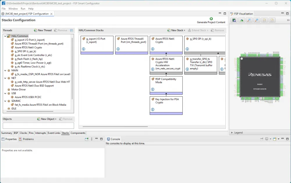
We are loading a full software stack including Azure RTOS ThreadX with drivers
Selected software components
Custom Board Support Files
v5.8.0
Arm CMSIS Version 6 - Core (M)
v6.1.0+fsp.5.8.0
Board support package for R7FA8M1AHECFB
v5.8.0
Board support package for RA8M1
v5.8.0
Board support package for RA8M1 - FSP Data
v5.8.0
Board support package for RA8M1 - Events
v5.8.0
Azure RTOS ThreadX
v6.4.0+fsp.5.8.0
Board Support Package Common Files
v5.8.0
Asynchronous General Purpose Timer
v5.8.0
Direct Memory Access Controller
v5.8.0
Data Transfer Controller
v5.8.0
Event Link Controller
v5.8.0
Ethernet PHY
v5.8.0
Ethernet
v5.8.0
Flash Memory High Performance
v5.8.0
I/O Port
v5.8.0
Octa Serial Peripheral Interface Flash
v5.8.0
Renesas Securyty IP on RA8 (RSIP7) Key Injection
v5.8.0
Real Time Clock
v5.8.0
Secure Cryptography Engine on RA8 (RSIP7) Compatibility Mode
v5.8.0
SD/MMC Host Interface
v5.8.0
Serial Peripheral Interface
v5.8.0
USB Basic
v5.8.0
FileX Block Media I/O Interface for RA
v5.8.0
SD/MMC Memory Implementation
v5.8.0
NetX Duo Ethernet Driver
v5.8.0
NetX Secure Crypto H/W Acceleration
v5.8.0
Azure RTOS ThreadX Port
v5.8.0
Porting layer for USBX
v5.8.0
LevelX NOR SPI Port
v5.8.0
FileX LevelX NOR I/O Interface for RA
v5.8.0
Azure RTOS FileX
v6.4.0+fsp.5.8.0
Azure RTOS LevelX
v6.4.0+fsp.5.8.0
Azure RTOS USBX PCDC
v6.4.0+fsp.5.8.0
Azure RTOS NetX Duo
v6.4.0+renesas.0.fsp.5.8.0
Azure RTOS NetX Crypto
v6.4.0+renesas.0.fsp.5.8.0
Azure RTOS NetX Secure
v6.4.0+renesas.0.fsp.5.8.0
Azure RTOS NetX FileX Servers
v6.4.0+renesas.0.fsp.5.8.0
NetX Duo BSD Support
v6.4.0+renesas.0.fsp.5.8.0
Controller Area Network - Flexible Data
v5.8.0
USB Composite
v5.8.0
Block Media RAM Implementation
v5.8.0
Azure RTOS USBX PMSC
v6.4.0+fsp.5.8.0
As a result of Smart Configurator’s work, we get the ra, ra_cfg, ra_gen directories with all the source files of intermediate software and drivers. I wouldn't say the process is easy. It takes quite a bit of fiddling to come up with a working configuration.
And from this point on, we stop writing code by hand
Naturally, it's impossible to create a proper finished product in Smart Configurator. It lacks a ton of essential features. I take this set from my own framework, which was presented in the controller repository MC50. Copy-paste it and start refactoring in VS Code for the new FSP RA8M1 API.
To compile successfully in VS Code, you need to install the GitHub Copilot and IAR Build extensions. If you have the STM32Cube extensions installed, you need to disable them, as they will conflict with the IAR extension and interfere with proper code browsing.
The first thing to do when starting work with GitHub Copilot is to create a detailed instruction file for the agent. My file is here. How well and unambiguously this file is written determines how much the agent will "fail" during code writing and refactoring iterations.
The best agent at the moment is, without a doubt, Claude Sonnet 4.
A new way to create a parameter database
Using agents immediately led to significant changes in the approach to organizing a parameter database. Previously, I used an MS Access database from the MS Office 365 package. It was quite convenient because it has a good table UI, which makes it easy to refactor and generate C source code. Although, I also had to write a Delphi application to make refactoring and entering parameters even more convenient. In the MC50 project, you can see this in the directory ParametersGenerator.
Now, when agents easily understand a JSON-format database and can refactor, supplement, and delete without error, it's much more convenient to keep the database in text JSON format.
The parameter database for this project is located in this file. Files are generated from it via scripts: MC80_Params.c and MC80_Params.h. The scripts themselves are located here .
The main script is this one - Generate_params_c_h_from_ParamsDB_txt.py
There is also a script Check_DB_format_field_consistency.py that checks the consistency of the database (just in case the agent makes a mistake). These scripts themselves were also written by the Claude Sonnet 4 agent.
It’s still unclear if an additional database description actually helps the agent, or if it spends the same time with or without it, but just in case I also gave the agents a database description — ParamsDB_Schema_Description.md. And I insert it into context when querying.
Idea on how to organize parameter management via the CAN bus.
If we manage the board over the CAN bus, we naturally want to control all parameters over the same bus. But there are quite a few parameters — how do we assign identifiers to them? Renumber? But if we constantly refactor both the controller and the control system, the numbering may stop matching — we might just forget to update it. Also, it may be necessary to retain support for previous versions of the parameter sets. The numbering will quickly cease to be sequential and consistent.
And the agent suggested an idea — to use hashes of the variable names. And immediately provided a script. Now, in the generated .c files, there are two tables with hashes. The table param_hash_table is designed for fast lookup of the parameter index by hash value when receiving packets, while the table param_index_to_hash_table is designed for quickly getting the hash by parameter index when sending packets. Hashes are computed from the variable name by taking the CRC16 of the variable name string. There is also a fast binary search function for the hash in the table.
Now, the packets over CAN contain not the parameter indices (which may differ between the central controller and the motor control board), but 16-bit parameter hashes. Hash collisions are not checked; instead, a script Check_DB_format_field_consistency.py is run to confirm that no collisions exist.
Initial debugging in the terminal
The agent wrote me a couple of excellent software debugging modules for the terminal via the USB VCOM port.
Firstly, a window for viewing the RTOS task status:
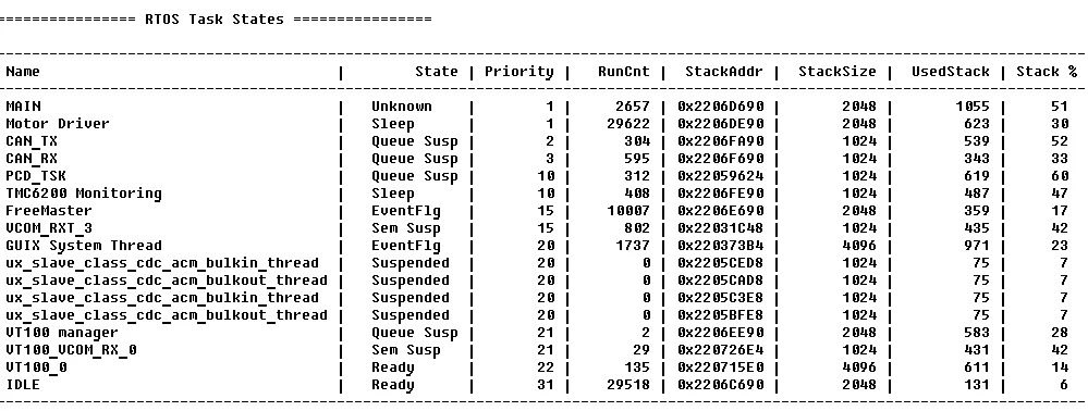
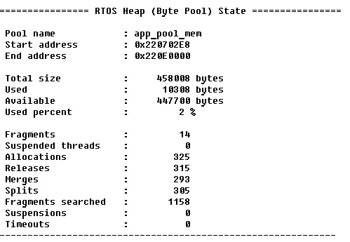
Then a window for monitoring dynamic memory consumption:
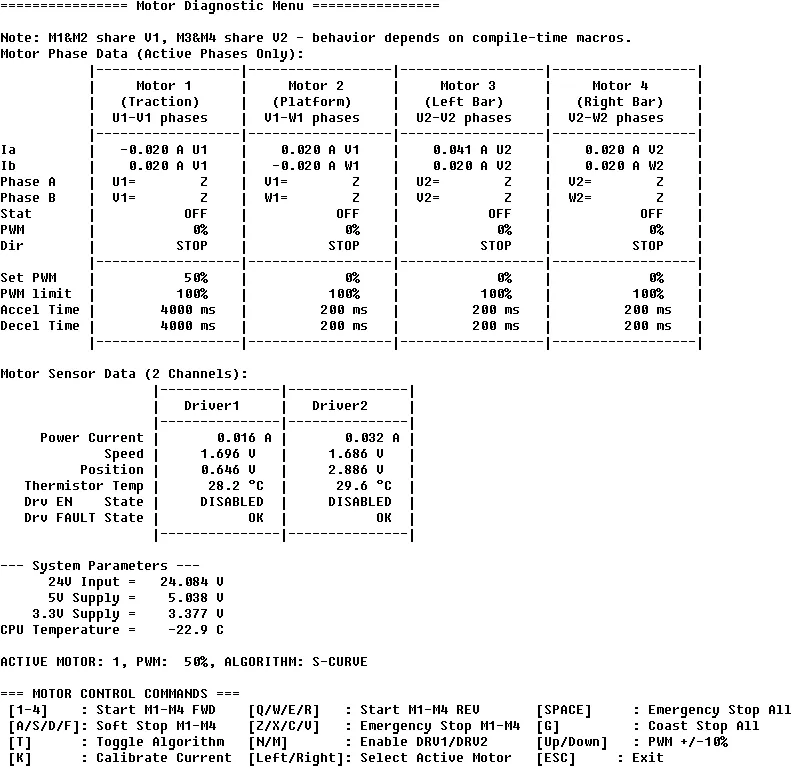
And of course, a window for controlling the motors:
Writing the terminal is the easiest, and it doesn't require special software on the PC. But the time comes to view graphs, and here FreeMaster comes into play.
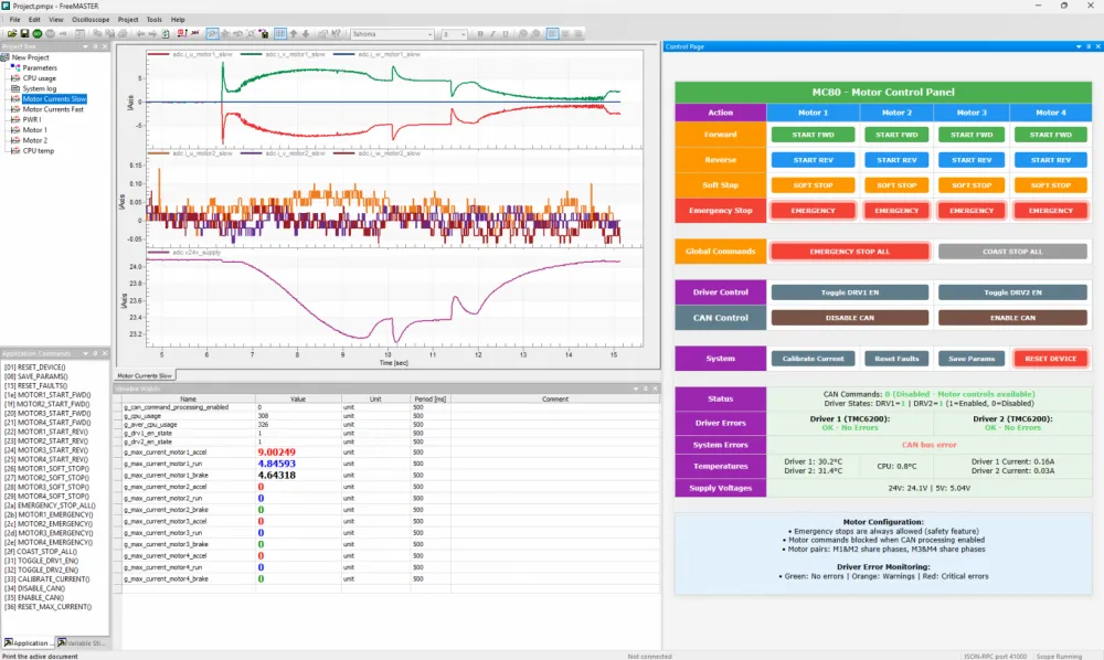
FreeMaster for motor control
The FreMaster control panel is an HTML page with a special API for the FreeMaster protocol. This protocol is independent of the transmission medium and can work over COM, VCOM, or even TCP/IP. And of course, the FreMaster control panel was also written by the agent Claude Sonnet.
Compilation and Debugging Issues
The agents generate code excellently, but they also parse and refactor XML — surprisingly well. In the project directory, there is a script Populate_MC80_4DC_Proj_ewp.py. It is supposed to recombine the IAR workspace file to insert new source files and remove deleted ones. But the agents can easily refactor the IAR workspace file directly without the need for additional scripts.
However, you shouldn’t skip another interesting script — Make_R7FA8M1AH_SVD_MOD.py. This script takes the original register description file R7FA8M1AH.svd and converts it to R7FA8M1AH_mod.svd. In the new file, the meaningless interrupt channel names IELx are replaced with actual interrupt vector names assigned in the project. In the RA8 family, there are no fixed vector numbers for peripheral interrupts, and the vectors just have anonymous numbers as they appear in the IAR C-Spy timeline. That’s really inconvenient. But the agent has given us a great script that solves this problem.
Unfortunately, trace engine operation via ETM in IAR for RA8 is not implemented. So, to start tracing I used the Ozone debugger from Segger. For this, there’s an Ozone.jdebug file in the project.
If you don’t have a JTAG/SWD debug adapter, you can flash the microcontroller via USB using the free Renesas Flash Programmer. But before powering on, you need to press and hold the manual encoder button on the board — the microcontroller will enter the factory bootloader mode.
The whole project is here - https://github.com/Indemsys/MC80_4DC


Write comment