- Network
- A
Wave Routing Method: Technical Proposals for Use
The main disadvantage of the wave routing method is the additional load created by transmitting the search packet in all directions, including in the opposite direction from the source. Therefore, a local-wave routing method is proposed, which involves organizing a wave search to find the shortest route in the network between a pair of nodes, but not in all directions, only towards the destination.
The wave routing method was first proposed by me for a message-switching network in an application to the Committee for Inventions and Discoveries under the Council of Ministers of the USSR No. 1515512, with a priority date of 18.02.70. It was assumed that the attributes of the network, in particular, the topology, were either initially unknown or could change significantly.
In this application, I proposed a method for finding the optimal path from the source node (UИ) to one of the destination nodes (УП). At the source node (UИ), a request was formed to select the optimal path to the destination node (УП). This request was replicated and transmitted through the network in a wave along many possible paths to the recipient. The task of selecting the shortest path between the source node (UИ) and the destination node (УП) was solved by the network's collection of nodes. The chosen path was remembered when transmitting the response from the destination node (УП) back to the source node (UИ).
It was formalized (currently located in Rospatent of the Russian Federation) in closed access (the Cold War was still on!) — a certificate of authorship No. 73 730 with a priority date of 06.09.73 for "a method of automatic message switching".
First, let's define the terminology
Terms and definitions will be used by me from the multilingual internet encyclopedia called Wikipedia, specifically from the following materials:
A Brief History of Telecommunications Development -> Telecommunication Systems and Networks -> Part 1. Methods of Message Transmission, Section 9.5 Routing Methods in Telecommunications Networks, page 30.
Let's extract information from these materials:
“Basic definitions. Route - a list of elements of the communication network (switching nodes, communication lines, communication channels), starting from the source node (UИ) and ending at the destination node (УП). Routing - the procedure that determines the optimal route based on given parameters in the communication network between switching nodes.”
Furthermore, on page 30, well-known routing methods are presented: terrain method and wave routing method.
Well-known Routing Methods
The relief method is usually used in systems with a routing server, which according to the seven-layer OSI model (quote from page 31): “collects and analyzes information about the network topology, and then transmits it to routers upon request, which are freed from the functions of creating PRI.” (PRI - plan for distributing information in the network).
The so-called wave routing method, in which (we quote from page 30) “upon receiving a request for organizing a route between a pair of nodes in the UIs, a search packet is formed, which is sent to all neighboring nodes. In neighboring UIs, this procedure is repeated. Thus, the search packet reaches all nodes in the network through a time equal to the time of its transmission along the shortest route.”
Disadvantage of the wave method, local-wave method
I further quote from the aforementioned materials:
“The main disadvantage of the wave routing method is the additional load created by transmitting the search packet in all directions, including in the opposite direction from the UP.” Therefore, a certain local-wave routing method is proposed, which “consists of organizing a wave search for finding the shortest route in the network between a pair of nodes from the UI, but not in all directions, only towards the UP.”
However, as the author of the wave routing method, I express my disagreement only with such a interpretation of the capabilities of the wave method and therefore propose to consider other options based on specific examples.
Firstly, the method was proposed as an alternative to the relief method, which is the main method using knowledge about the network topology; secondly, we were primarily interested in such important characteristics as the survivability of the network and the message transmission time.
The wave method does not understand what the opposite side of the UP is. For it, this may simply be the route that is the shortest with the least probability among others. However, there are hypothetical cases where such a route may turn out to be the only one.
The defining parameter of the wave method is the TIME for delivering messages, which automatically takes into account both the topology and the bandwidth, as well as the loading of edges and nodes in the network.
Example: a network of 13 switching nodes
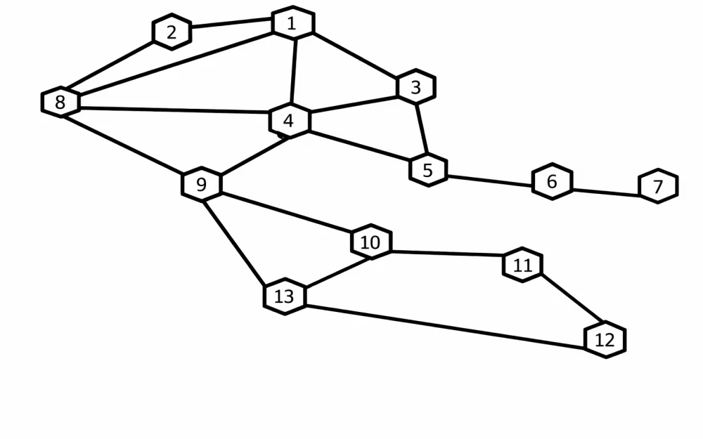
The essence of our technical solution will be explained through examples, considering the use of the proposed technical solution in the dynamics of creating and operating a data transmission network. The graph of the communication network, considered as an example, is shown in the figure.
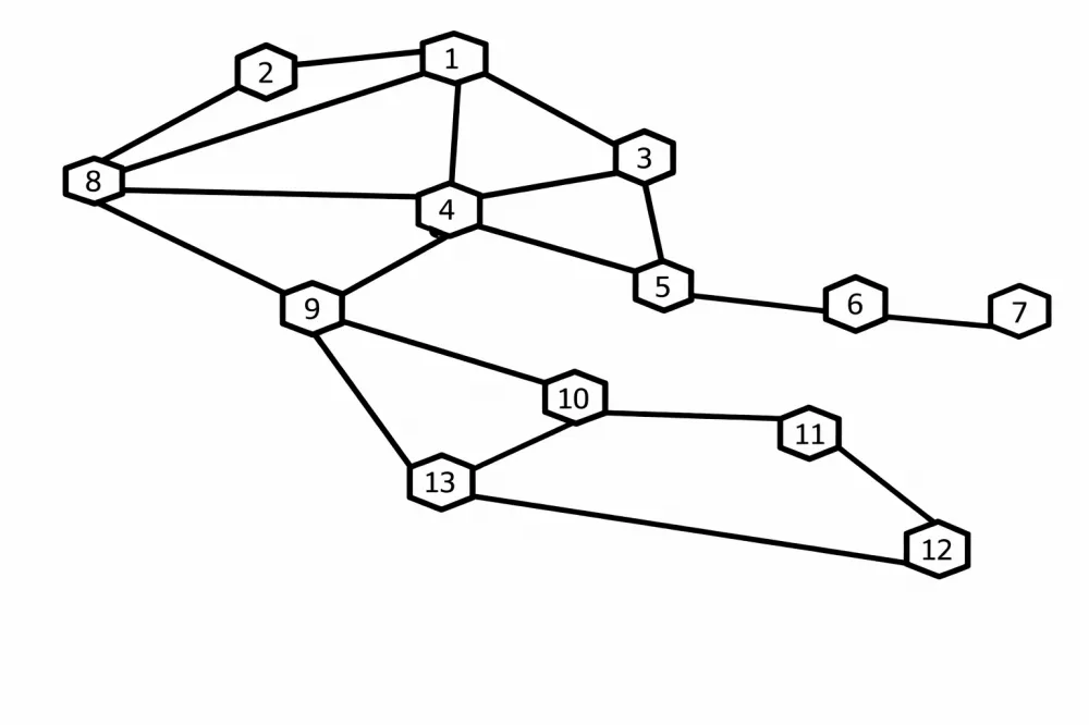
This is, for example, a network of 13 switching nodes (UK). The data transmission channels in the directions of the network are as follows: UK8-UK2, UK2-UK1, UK1-UK3, UK3-UK4, UK3-UK5, UK4-UK9 all at a speed of 2400 baud, the others at a speed of 50 baud.
TASK #1
UK13 is put into operation. In it, the direction UK13-UK9 is at 2400 baud, the others at 50 baud. It is necessary to build lists of the shortest routes between UK13 and all other UK nodes in the network.
For this, a multicast request is formed in UK13 with the following content: address of UK13 (address of UI), priority of the request transmission (in this case, the highest), number of required routes (for example, two), addresses of all UK from (1 to 12), for which it is required to establish lists of the shortest routes.
This request from UK13 is transmitted through all outgoing directions from node UK13 and reaches the transit nodes. Next, using the example of a transit node, for instance, UK8, we will explain the algorithm for processing the request.
When receiving the first copy of the request, UK8 finds its address (UK8) among the addresses and remembers this copy of the request along with the number of the incoming direction from which it was received (in our case, the direction number UK13-UK9-UK8). In this copy of the request, the address UK8 is marked as "served" and it is retransmitted through all outgoing directions from UK8, except, of course, UK8-UK13.
In our example, the second copy of the request may come from UK4, passing through a long transit route UK8-UK2-UK1-UK3-UK4-UK8, however, this copy of the request will be ignored due to the marking of the address UK8 in it, since it is a copy generated by UK8 itself.
The third copy of the request will arrive from UK9, passing through the route UK13-UK10-UK9-UK8. Since it will contain the "unserved" address UK8, it will go for processing, during which the communication direction for the second priority route between UK13 and UK8 will be remembered. But this is a copy of the stored request; it will be destroyed and will not be subject to further broadcasting.
Thus, UK13 learns that it has two optimal paths to UK8. It is worth noting that UK8, when choosing the next route, sends a response in the chosen direction with the priority number of this route in the lists.
It is also important to note that a hypothetical case was considered, where all UKs appear in the network simultaneously. In practice, this is not the case: UK13 is put into operation when the other 12 nodes (or part of them) are already functioning, which means that they already have lists of the shortest paths, and nothing prevents making waves locally along the previously chosen shortest routes.
Thus, lists of the shortest routes are formed without considering queues in transit UKs. It is noted that several routes are formed between UI and UP, which allows us to speak of the emergence of a virtual network of the shortest routes between UI and UP in the data transmission network.
By the way, it is possible to include other requirements in the request for the shortest routes network, for example, to filter the shortest routes taking into account the class of channel capacity.
TASK NO.2
So, the lists of the shortest channels by speed have been constructed. A network of shortest routes from UI to UP has been created. In this network, various procedures for optimizing the management of information flow distribution can be introduced, for example, the widely known procedure for assessing system quality by average.
This means that the shortest routes can be ranked by message delivery time. The aforementioned request is reformulated, in which the addresses of UP (possibly one, possibly several, possibly all) with the lowest (as for all messages) priority of its transmission are specified.
This request is transmitted in the local wave network to each address along the previously selected shortest routes, but now becoming at the end of the message queue. Further processing is similar to that outlined above. Ultimately, a correction of the optimal path lists is made, taking into account the average message delivery time.
At the same time, the same wave routing method is used, but now in a dedicated area of the network with local wave transmission. And everywhere, the time prevails in the samples, not the topology.
TASK NO.3
A global external impact has been produced on the network, which has led to significant changes in it, resulting, in particular, in the failure of control centers. It is clear that this will require solutions similar to those outlined in Task No. 1.
Two-Stage Use of the Wave Method
Thus, from the point of view of minimizing the flow of service information (i.e., requests), it is advisable to use the wave routing method in a two-stage manner:
at the first stage, particularly when introducing the UIs into operation, by creating lists of the shortest routes from the UIs to the CP through the transmission of a multicast request across all possible routes;
at the second stage, during the optimization of message distribution in the network of the shortest routes through the transmission of a local wave.
Conclusion: Comparative Analysis
In conclusion, a brief comparative analysis of the terrain method and the wave routing method.
Here you have a data transmission network. On a piece of paper, you depict this network as a graph of the network. The first thing that comes to mind for a person is the topology of the network; the network administrator sets the configuration of the network.
Next, understanding that besides topology there is something else, the administrator adds various attributes to the edges of the graph, so to speak, "for good measure," such as edge costs or bandwidths and so on. There are protocols that process the attributes; there are quite a few of them, as well as developers.
There may be some synthesizer of everything into a single policy (the same network administrator). But there is also a business policy. If the administrator is a businessman, then he can, based on his business policy, ignore all these "for good measure" attributes, guided only by cost.
Incidentally, it seems that the nodes themselves are out of the game. Is there something (or someone) that manages everything or not? And where is it? This something is called a "routing server" in Wikipedia. In fact, hiding behind the scenes is the network administrator (director, boss).
From the perspective of systemic ideology, the system is an ordinary centrist semi-automaton, and this semi-automaton is managed at the center by the network administrator.
Now about the wave routing method. It is necessary to create an Automated Control System (ACS) for solving specific tasks. In the ACS, the data transmission network serves as a tool. The attributes of such a data transmission network are unknown; moreover, they can change significantly.
What is the most important, fundamental parameter of such networks that synthesizes all network attributes, except for cost?
I answer - the delivery time of information from the User Interface (UI) to the Control Point (CP).
The wave method, unlike a centralized semi-automatic system, allows for the construction of a simple, decentralized, fully automatic system. The center should only determine and require adherence to certain target parameters.
Lists of the shortest routes can be used for both virtual channel mode and datagram mode.



Write comment