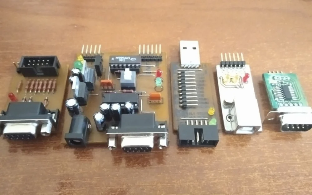
- DIY
- A
My DIY Programmers
Many years ago, on a beautiful day, after reading about microcontrollers, I decided to try working with these devices. After all, it's convenient; one chip can replace a complex digital circuit. Making a printed circuit board and soldering the scheme is not a problem. However, a programmer is necessary for programming microcontrollers.
I went to the market, which is called "Radiobalka" here, and looked at the programmers and their prices. They were either very expensive or poorly made. Buying was not for me, I thought, I can make these myself.
The first microcontroller I programmed using Gromov's programmer and the UniProf software. It was a thermostat on the ATtiny2313. I assembled the programmer on the fly, didn't etch the board, just scratched the foil in the phenolic. Instead of a connector, I plugged wires into the pins of the COM port. When the circuit worked, I jumped for joy because before, the words "flash" and "programming" would leave me stumped, I thought only gods could do it. But programming with such a programmer was wrong.
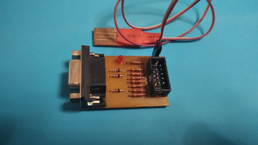
So, I used a laser printer to make and etch a proper board with connectors and USB power.
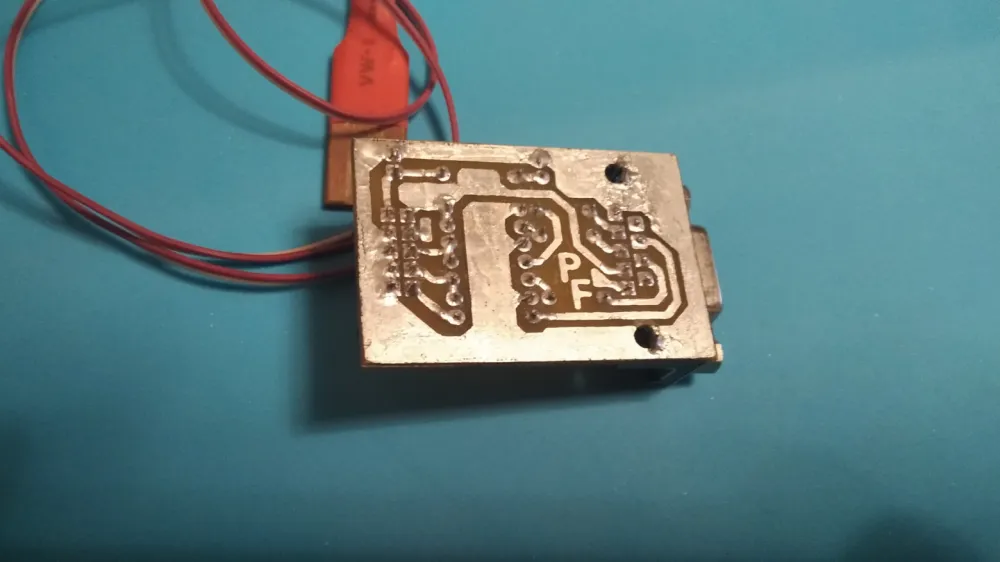
This board requires a COM port extender.
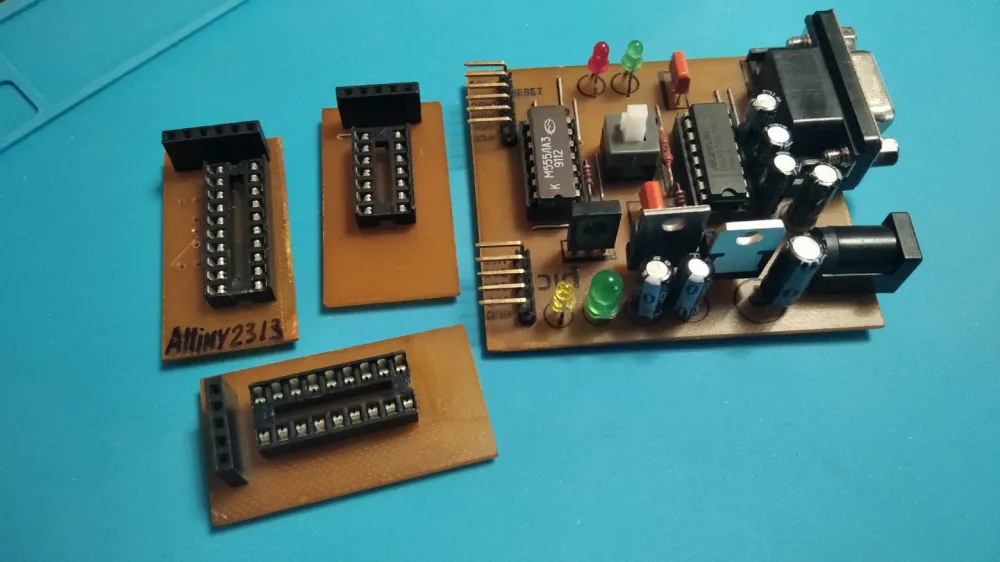
After some time, I needed a programmer for the PIC16F84A microcontroller, which is a bit different and requires higher voltage on the Vpp pin. I found an interesting programmer online that could program both PIC and AVR microcontrollers. I slightly modified the board suggested by the author.
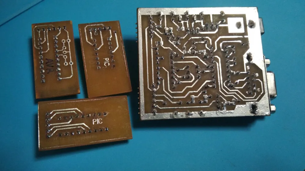
The programmer works from the COM port. For proper operation, the programmer requires external power of more than sixteen volts. It works with IC-Prog and PonyProg programs. When I first assembled the board, it didn't work. After checking, I found that I had mirrored the board incorrectly. Then I had to turn the pins of the IC around and place them upside down, and the programmer started working. Later, I etched a new, corrected board and reassembled it according to the correct schematic. For convenience, I made transition boards for different microcontrollers.
Later on, the COM port ceased to be the standard for PCs, and I no longer had any computers with a COM port. The need arose to switch to USB.
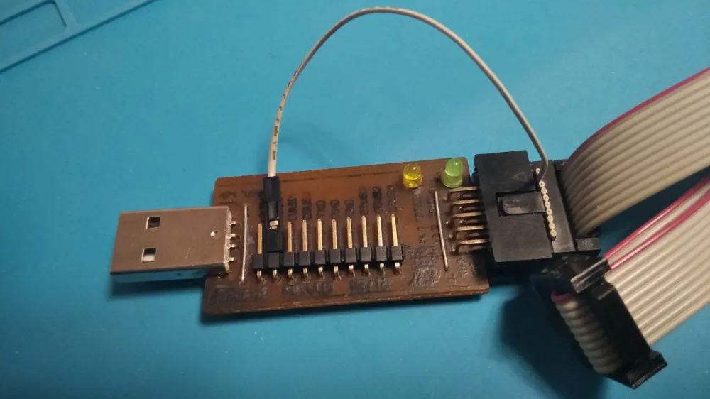
I found a decent programmer APU-2 on the FTDI232 chip on the network. This programmer, in addition to the ISP connector, also has pins for UART, allowing it to program Arduino.
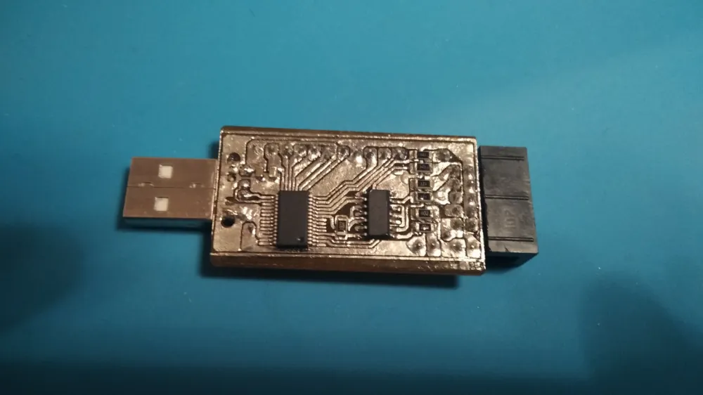
The programmer works on the Bitbang principle. The peculiarity of this board is that the power supply does not come to the ISP connector, so I had to modify the programmer’s ribbon cable. It was probably designed for programming five- and three-volt microcontrollers. The author uploaded the PCB file, and I replicated it. In the author's article, there is a link to the Sina-prog program, configured for this programmer.
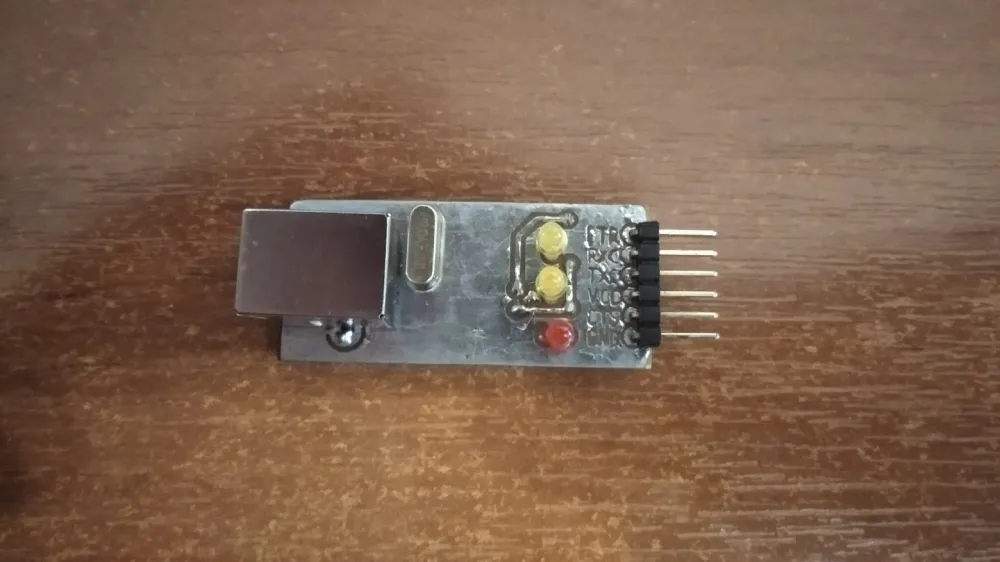
Later, when I switched to Arduino, I made a USB-UART converter using the inexpensive CH340g chip. I assembled it according to the datasheet schematic and just added LEDs for power and data transmission lines.
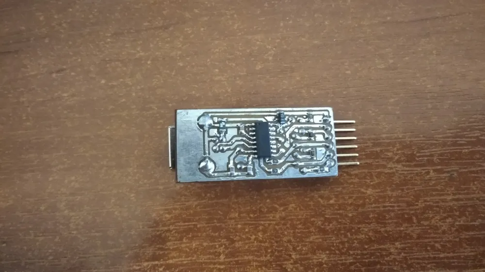
This was my first dual-layer board. The datasheet also had a schematic with optocoupler isolation using PC814 optocouplers. At first, I made it according to this schematic, but it didn’t work. I didn’t install a couple of switches that were recommended in the description, but not mandatory. Then I made it according to the standard schematic.
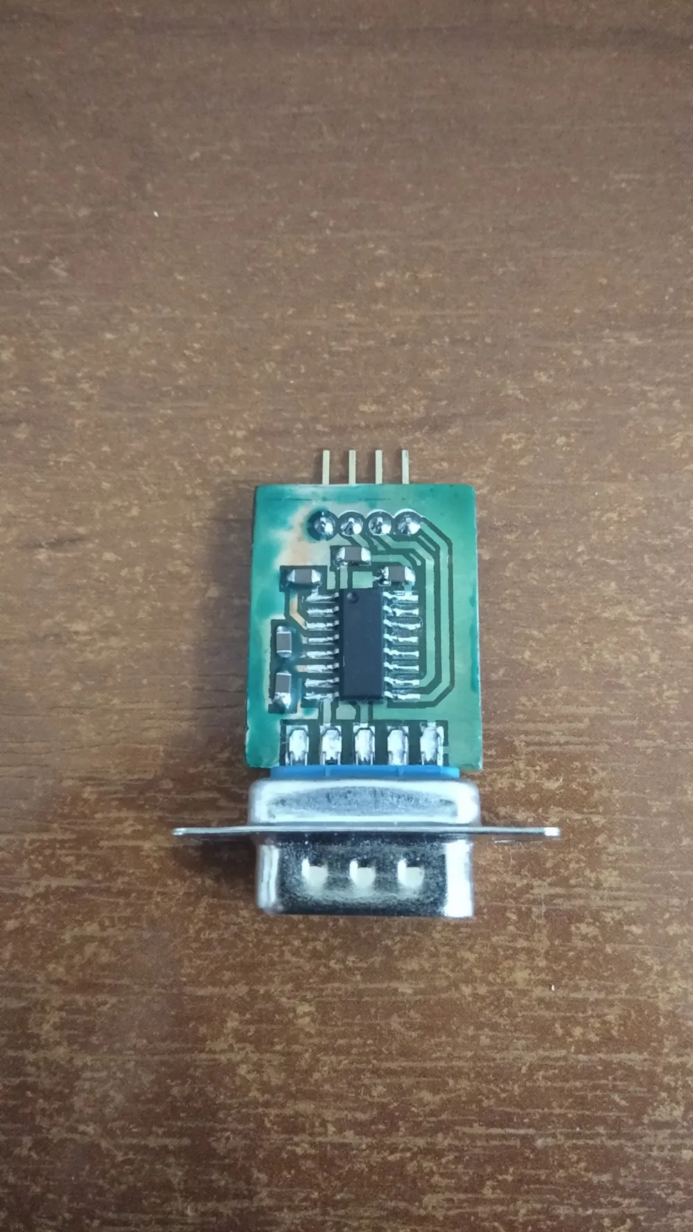
Recently, I needed a COM port for flashing a Chinese clone of a Mitsubishi PLC. The purchased converter didn’t work, so I opened it up, something unfamiliar is identified as CH340, but the pinout doesn’t match. When shorting RX and TX in the terminal, an echo occurs. The cable works, but not quite right. I think it’s missing the signal level converter MAX232. I don’t need a full COM port. I made a simplified signal level converter from the COM port to UART.
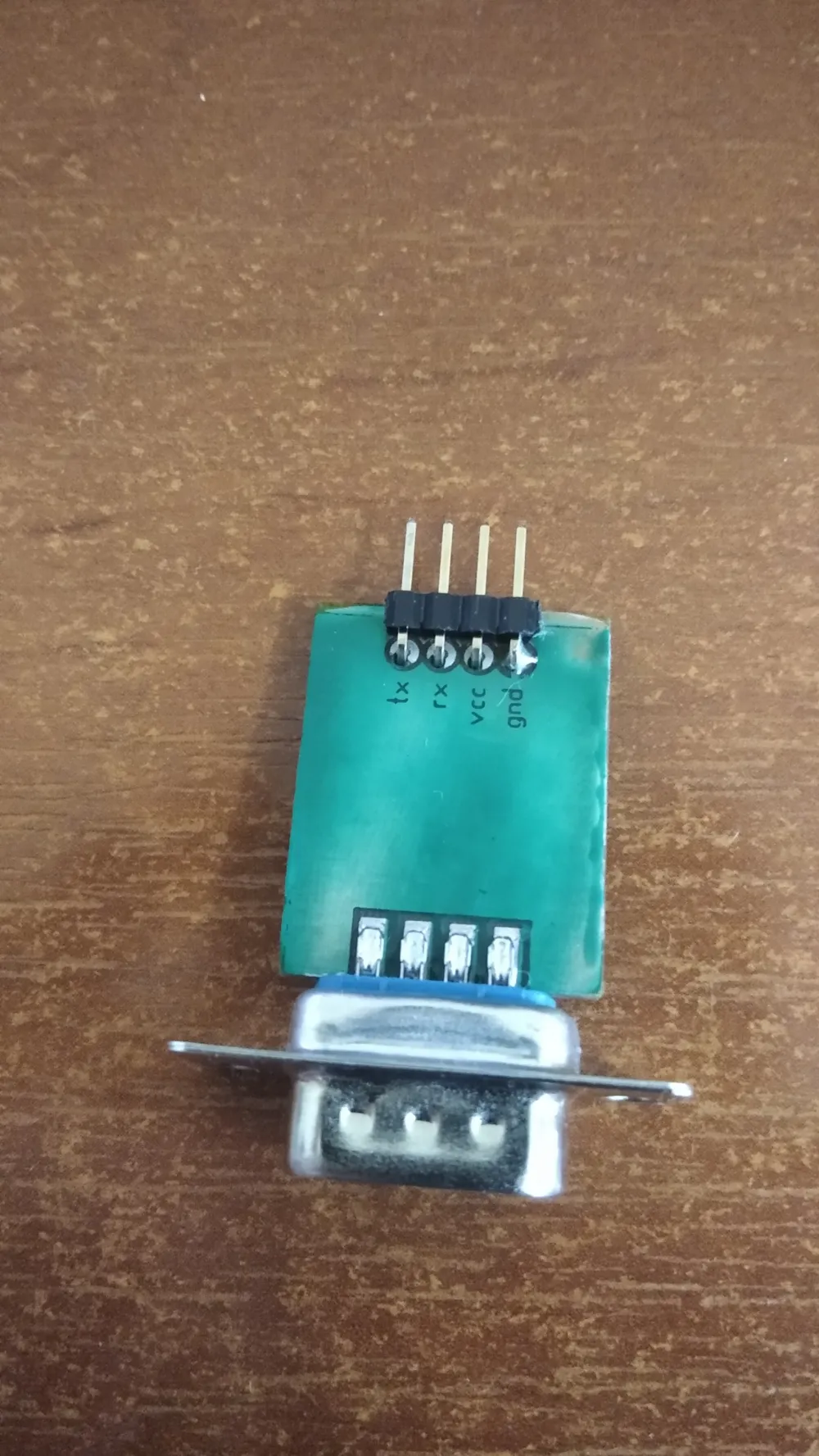
I made the board using photoresist and tried to make a mask for the first time. I got myself, the table, and everything nearby covered in this green stuff, but the mask turned out okay. Together with the USB adapter, the controller was successfully flashed.
Of course, some will say it wasn’t worth the effort, it’s better to just buy it and not worry. I was curious to make it myself, gaining skills and experience.
Write comment