- DIY
- A
Weekend project — autonomous RGB ball for the Christmas tree
Hello tekkix members! On the eve of the New Year, I want to share with you my experience of making a craft based on a free devboard from a conditionally disposable product. In the article, we will figure out how to control addressable LEDs using the PUYA PY32F002BF microcontroller and how to monitor the battery charge using the ADC.
Lyrical digression.
In our age of accessibility of everything, a question may arise - "Why are you doing this?". This is exactly the question my son asked me, looking at the flashing lights. After all, you can buy an addressable garland for the Christmas tree with a bunch of modes and a phone app. I thought about it and answered: "I want this thing to flash exactly the way I want it to." Then I thought again and came to the conclusion that most likely the found board did not give me peace. I disassembled it, saw the controller, LEDs - probably you can control it and put it in a drawer. Then a colleague at work found the same board and suggested soldering an STM to make a conditional Christmas tree in the form of a board in a USB port to enhance the New Year's mood at the workplace. It already sounded like a challenge. Why solder if everything is already on the board. And challenges and responses to them are evolution. I found with interest that the knowledge gained in such seemingly useless projects finds application in more complex, necessary and paid tasks.
So, let's get started. For a quick start, you need to read the article. It describes how to set up the toolchain and prepare the popular "whistle" ST-LINK V2.
Preparing the hardware
Carefully disassemble the found (selected with a lecture on the dangers of bad habits from a friend/girlfriend/teenager), not yet prohibited in the Russian Federation, disposable product. I carefully sawed (not through) part of the seam of the plastic case and opened it with a twisting motion of the screwdriver in the slots. The board is held on two self-tapping screws. Self-tapping screws in the collection, dispose of the rest according to the rules of separate collection.
Safety requirements log entry. Scheduled briefing on safety measures when working with lithium-containing batteries. Such elements are fire hazardous and require careful handling by trained and authorized personnel!
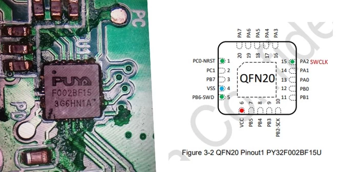
Using the soldering method, disconnect the battery (do not short the contact pads with the tip!) from the board, and remove it from persons who have not passed the admission and have not signed the safety log. We inspect the board. We determine the marking of the microcontroller, look for documentation. We find the pins for the programmer.
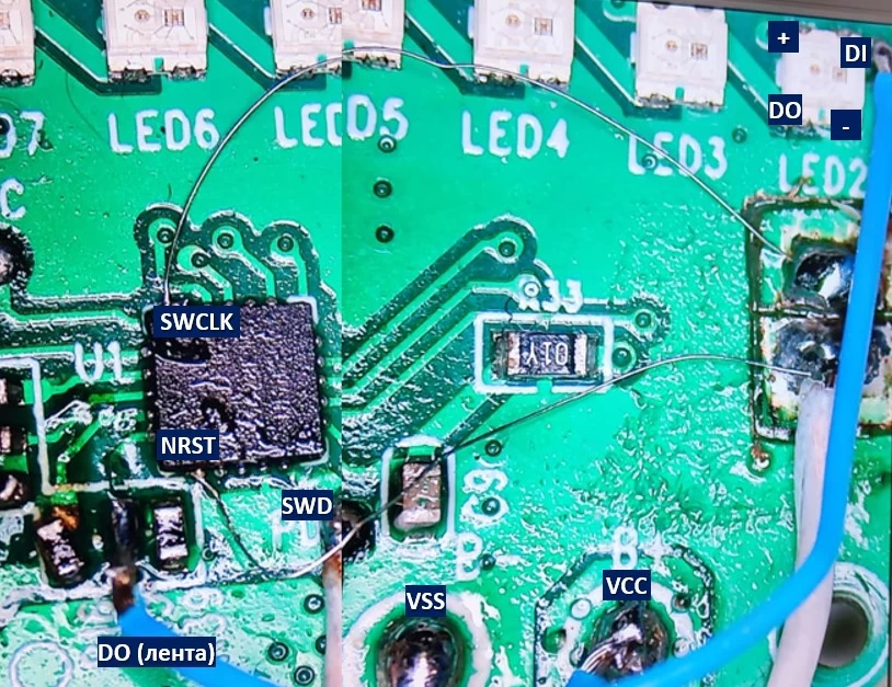
Armed with a tester in continuity mode, we look for places to solder the wires. At this stage, I was slightly stunned. The first and fifteenth pins are not routed, as well as the data pins on the USB connector. Most likely, the controllers go to the assembly line already flashed. The most difficult part of this project is to solder to pins 1 and 15. I did it as follows. Using the scribing method, I prepared two pads in a free space of the board for soldering wires. I soldered two wire strands (approximately 0.15 mm) to these pads. I soldered the other ends to the chip pins by poking the tip into the pin. I soldered without a microscope. The first pin worked immediately, the second on the third attempt. We check with continuity.
Now it's time to insert the programmer and send the command pyocd erase -t py32f002bx5 --chip --config ./Misc/pyocd.yaml. Unlike my previous experience, I did not have to catch the moment the factory firmware started. The chip was erased immediately, you can continue.
Connecting the tape
In the factory topology, the tape is connected to pin 7 (PB5). According to the datasheet, this pin can be: SPI_NSS, USART_RX, TIM1_CH3, TIM14_CH1. And here I did not see a quick way to start the tape. Most likely, the Chinese controlled the tape using PWM on the timer and DMA (as here). I like this solution because there is no need to change the topology. But I won't master it quickly, and we have a weekend project. I found a ready-made solution from IOsetting, the path to the example is Examples/PY32F07x/HAL/SPI/WS2812_LED. Control of the tape is based on sending the necessary signals through the SPI output. I connected the tape to pin 20 (PA7 - SPI_MOSI, cut the track from PB5). It's time to write embedded special software.
Programming the program
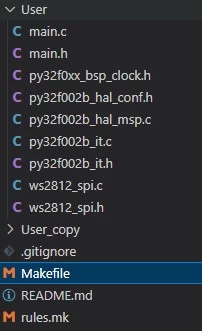
All project files are located in the User folder.
In the Makefile, uncomment our microcontroller - MCU_TYPE = PY32F002Bx5. In the file py32f002b_hal_conf.h, open the necessary peripherals (ADC and SPI - #define HAL_ADC_MODULE_ENABLED and #define HAL_SPI_MODULE_ENABLED). In the file 32f002b_hal_msp.c, add initialization and deinitialization of SPI.
void HAL_SPI_MspInit(SPI_HandleTypeDef *hspi)
{
  GPIO_InitTypeDef GPIO_InitStruct; // Structure for storing settings

  if (hspi->Instance == SPI1)
  {
    __HAL_RCC_GPIOA_CLK_ENABLE(); // Clocking
    __HAL_RCC_SPI1_CLK_ENABLE();

    /* PA7 -> AF0 -> MOSI */
    GPIO_InitStruct.Pin = GPIO_PIN_7; // SPI mode setting
    GPIO_InitStruct.Mode = GPIO_MODE_AF_PP;
    GPIO_InitStruct.Speed = GPIO_SPEED_FREQ_HIGH;
    GPIO_InitStruct.Alternate = GPIO_AF0_SPI1;
    HAL_GPIO_Init(GPIOA, &GPIO_InitStruct);
  }
}

void HAL_SPI_MspDeInit(SPI_HandleTypeDef *hspi)
{
  if (hspi->Instance == SPI1)
  {
    __HAL_RCC_SPI1_FORCE_RESET();
    __HAL_RCC_SPI1_RELEASE_RESET();

    HAL_GPIO_DeInit(GPIOA, GPIO_PIN_7);
  }
}
In the file ws2812_spi.h, set the number of LEDs in the tape - #define WS2812_NUM_LEDS 9.
Since working with addressable tapes is well described and information is available online, we will not consider this in detail in this article. We are interested in the functions of setting the LED color ws2812_pixel(uint16_t led_no, uint8_t r, uint8_t g, uint8_t b) and sending the formed array s2812_send_spi().
In the original version of the circuit, power is supplied to the LEDs through transistor Q3 (apparently, to be able to turn off the strip when the device is idle). The transistor is controlled via PB3. This pin will be configured as GPIO. In the main.c file, we will add the inclusion of header files and functions for configuring input-output ports and SPI (APP_GpioConfig()). From the example in the main loop, we will start a simple color change of the entire strip.
....
int main(void)
{
  uint8_t i = 0, r = 0, g = 0x60, b = 0xC0; // Colors with offset, otherwise we will
                                            // only have white color

  HAL_Init();
  APP_GpioConfig(); // Configuring the previously described peripherals
  HAL_GPIO_WritePin(GPIOB,GPIO_PIN_3,0); // turn on the strip - 0, turn off - 1

  ws2812_pixel_all(r, g, b);
  ws2812_send_spi();
  while (1)
  {
    i = (i + 1) % WS2812_NUM_LEDS;
    ws2812_pixel(i, r++, g++, b++); // Setting the color
    ws2812_send_spi();              // Sending data
    HAL_Delay(20);
  }
}
...
We compile and flash. After several trials and errors (for example, I did not describe the function prototype at the very beginning and tried to call it) the strip happily lit up.
Where to get "effects"?
Simple color change is good, but monotonous and boring. I started looking for how to implement something fun and festive (like a rainbow) without libraries (like NeoPixel). The search led to the LED Strip Effects Generator. This is a constructor where you can set the parameters of your strip, choose an effect (or several) and get the code for Arduino as output. After some minor adjustments (I changed the sending functions and some effect parameters), I managed to run the rainbow on my device. To avoid cluttering everything with code here, I will refer to the github of this project.
Measuring supply voltage
To monitor the battery charge, we will use the ADC. Having a list of ADC channels and their corresponding microcontroller pins, I started looking for dividers. And, it seems that the voltage measurement was taken at the moment of turning on the heating elements, then it was saved and displayed according to the logic of the factory program. An alternative to this method was the method of measurement by the ADC_CHANNEL_VREFINT channel. For this, the ADC configuration function (APP_AdcConfig(void)) was added. The measurement itself is extremely simple.
    APP_AdcConfig();
    HAL_ADC_Start(&AdcHandle);
    HAL_ADC_PollForConversion(&AdcHandle,1000000);
    adc_value[0]=HAL_ADC_GetValue(&AdcHandle);
    T_VCC=adc_valie[0];
There is a formula in the datasheet for converting the readings to Volts, but without proper debugging tools (I had to solder the UART), I did not get clear results. I found the values in the readings by scientific trial and error (I changed the supply voltage on the laboratory power supply and watched how many LEDs lit up, simultaneously changing the conditions for their lighting in the readings). Of course, I will not insert this code here, but anyone can see it on the git mentioned above. The last question for me was the charge indication. The charging process is organized using the Li-Polymer Charger LP-4068. In the original circuit, the fifth pin of the LP-4068 is connected to the microcontroller input and is monitored programmatically. I looked at this pin with an oscilloscope when the external power supply was connected. A periodic pulse appeared on it, this pulse most likely turned on the LED.
I did not find a quick solution to use this (most likely an external interrupt-flag setting-time control is used). But, at about this stage, it turned out that the microcontroller has a built-in temperature sensor. And during the charging process, the LP-4068 heats up. By increasing the temperature, I can show the charge indication. The sensor is connected to the same ADC channel as ADC_CHANNEL_VREFINT. Depending on what needs to be measured (supply voltage or temperature), the ADC channel needs to be reconfigured. The general algorithm of operation looks like this:
after power is applied, the peripherals are configured, and we enter the main loop;
if the supply voltage is more than 2.9 V and the temperature is not higher than 27 degrees - turn on the rainbow for a minute (the rainbow gradually accelerates, then blue and red lights burn like a police flasher);
turn off the strip for 30 seconds;
turn on the charge indication, then the temperature.
repeat the cycle.
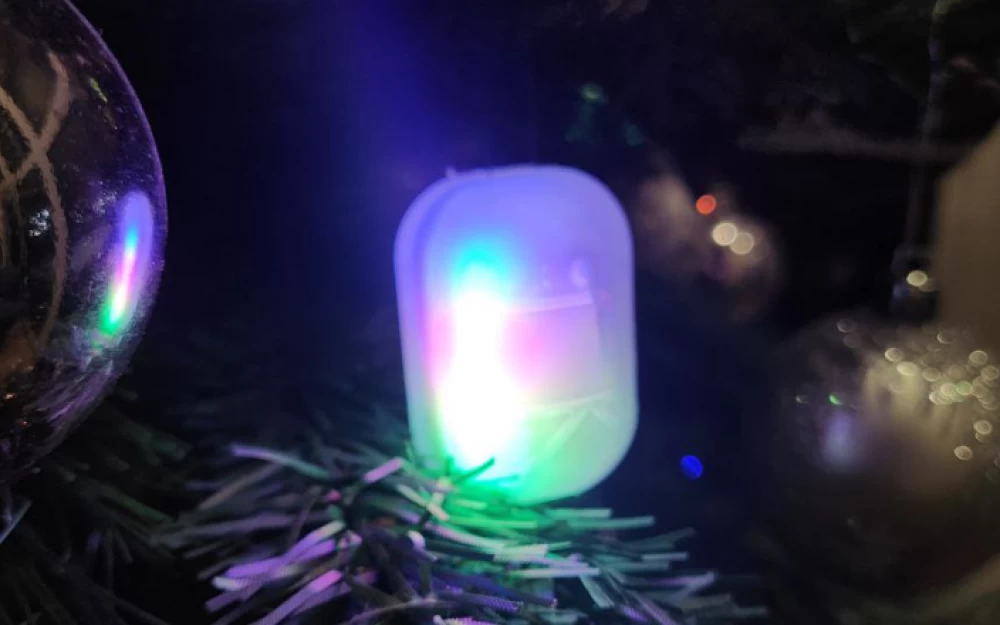
When heated above 27 degrees, only the charge and temperature indication works. When the supply voltage is 2.9 V or lower, one LED blinks red sadly. Below is a video of the main operating mode in the project position on the Christmas tree. Warning, bright light flashes! (very difficult to shoot with a phone, the colors are different in real life)
Below is the charge and temperature indication. When heated, the blue LEDs gradually turn off, leaving only the red ones. As a case, I used a transparent "yolk" from a chocolate egg (painted inside with acrylic from a spray can).
How autonomous is it?
The circuit consumption in the most expensive mode is about 47 mA. On the supplied battery, it works a little more than 12 hours. To increase the operating time, you can reduce the brightness, increase the idle time, and at the same time put the controller into low power mode. According to the datasheet, 1.7 µA is promised in STOP mode.
Conclusion
The "ball" turned out to be quite unusual. Those who see it ask what it is and how it works. They are even more surprised by what it is made of. What else can be made from this board? If you print a rotating base, you can get a circular screen with mechanical scanning. The circuit works from 2.4 volts. You can make a badge or pendant for the Coin Cell Challenge.
I wish you creative success in the coming New Year!





Write comment