
- Network
- A
IPsecHub+. Complex Scenarios
Hello everyone! Nikolay Edomsky here, head of the network engineers group at EDINY TSUPIS.
I present to your attention the fourth article in the "IPsecHub+" series.
In the previous article, we looked at the scheme for building an IPsec concentrator based on the so-called escalator topology. Now, we’ll look at examples of more complex scenarios, such as when regulatory requirements must be met, when branches with overlapping address spaces need to be connected, and so on.
Right away, I’ll say that for now, these scenarios are considered without taking into account a fault-tolerant IPsec concentrator scheme. The description of a fault-tolerant scheme will be provided in the next article. It will significantly complicate our topology, so for simplicity’s sake, we’ll look at the connection of complex scenarios using the standalone concentrator as the example.
So, what might we encounter?
Hiding DC or branch addresses
Certain tasks, usually related to information security, involve hiding DC addresses in branches, or vice versa—the DC shouldn’t see the real branch addresses. Such requirements are sometimes found in high-security zones (DMZ). This is also sometimes relevant when you need to integrate a particularly old branch into a new addressing scheme. Sometimes a single network that’s not “feng shui” at all can complicate configuration considerably, requiring exceptions in prefix lists, making configs longer, and so on. And in the end, it just doesn’t look good. At the same time, changing the branch’s addressing in some cases is either impractical or simply impossible.
Let’s look at an example where we want to hide one of the branch addresses in our infrastructure. Someone decided to assign the address 192.168.1.1 to the resource we need in the branch. Because of that, remote users working over VPN are always complaining about the resource being unavailable. This happens because 192.168.1.0/24 is one of the most popular subnets for home routers.
What do we need to do to hide the real branch address?
Instead of the notorious 192.168.1.1, we’ll assign it a neutral 100.64.1.1 from RFC6598. The main substitution procedure will be done in the target red VRF.
In the same VRF, we’ll need to create the corresponding DNAT rule.
Don’t forget to also leave a route to the real host address in this VRF. This allows correct routing of traffic after the DNAT procedure.
Add a route to the surrogate address on the firewall and in the VRF ipsecTo. Here, you’ll need to specify the corresponding veth interface address as the gateway, which is located in the target red VRF.
This is what we end up with, see Fig. 1.
In the lower part of Fig. 1, you can trace how the headers of the IP datagram will change as all DNAT rules are applied. In this case, we only have one.
The original objective is achieved. The only place where we’ll operate with the undesirable address 192.168.1.1 is the isolated red VRF. Everywhere else in the network, the undesirable address will be “feng shui.”
The situation with address conflicts
Let’s now look at a more complex scenario. Often, connecting a remote site can be associated with additional difficulties because the remote site is not under our management. In addition to diagnosing issues with multivendor IPsec, we might also encounter, for example, the problem of overlapping address space between the remote site and our data center. We might also face BGP AS number overlaps. More on that later.
How can we solve such issues using our concentrator? Now we’ll need to do the following:
Assign a surrogate address to the remote host.
Also mask our connections from the data center with a surrogate address.
It might seem like everything is quite straightforward, and we can carry out the procedure of translating the destination host and masking our own connections in the same target red VRF. In terms of NAT, this is entirely possible. But in terms of routing, it won’t work, since we won’t be able to route the traffic correctly. The source and destination addresses will be in the same subnet or even identical.
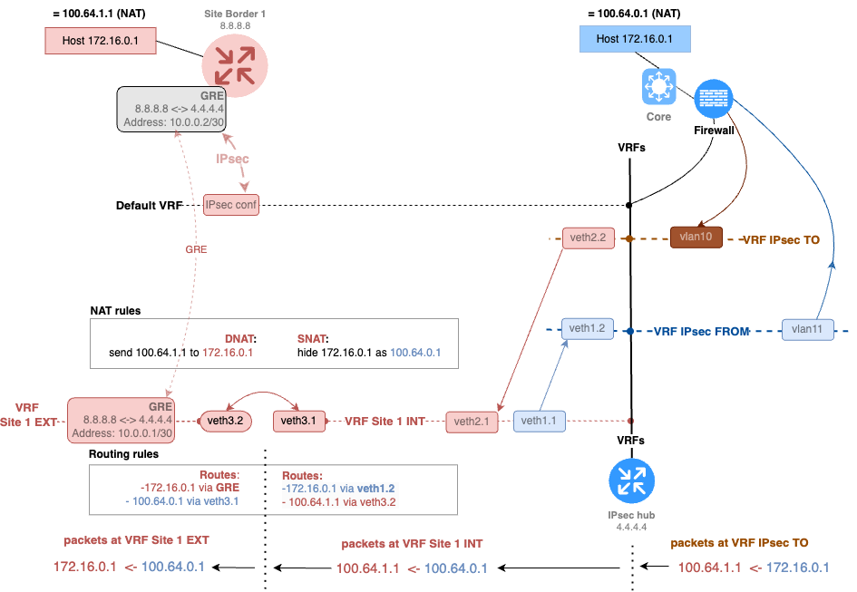
Let’s look at an example like this. The host in the branch office has the same address as the host in the data center — 172.16.0.1.

What can we do in such a situation? The so-called cascading of the target VRF helps here.
Create a VRF Site 1 INT: we need to create a first-tier VRF where we first mask our address with a surrogate. Let’s call it “Site 1 INT” because it routes traffic to the real address of our data center (internal addresses).
In this same VRF, we definitely need to mask our real address with a surrogate.
Create a VRF Site 1 EXT: next, we proceed to create the “Site 1 EXT” VRF, where the GRE to the remote site is placed.
In VRF Site 1 EXT, we will translate the surrogate address of the remote site to the real one (external addresses).
And finally, these two VRFs need to be connected via veth to provide connectivity between them.
One more thing related to routing. In the “site 1 INT” VRF, we need to create a route to the surrogate branch host 100.64.1.1 via the veth in the “site 1 EXT” VRF. Similarly, in the “site 1 EXT” VRF, we create a route to the surrogate data center host 100.64.0.1 via the veth in the “site 1 INT” VRF.
See the resulting diagram in Fig. 3. The diagram is fairly large, so it is best to click it to enlarge.
With this setup, we were able to completely isolate overlapping addresses between the branch and the data center. But what if we have an overlap not just of hosts, but of entire subnets?
Accepting overlapping subnets
I propose to consider a scenario where we provide interconnection with a counterparty using an entire subnet, not just a single target host. In this case, the Netmap technology can help us. It is not supported on all platforms, but, for example, it is available with iptables on Linux systems. With its help, we can provide coverage not just for hosts, but for entire subnets. For example, we can replace the branch’s 192.168.1.0/24 subnet with 100.64.1.0/24. In such a configuration, the host will be covered by a corresponding surrogate address according to the rule “the first three octets are changed, the last one remains.”
Let’s look at the resulting diagram, see Fig. 4.
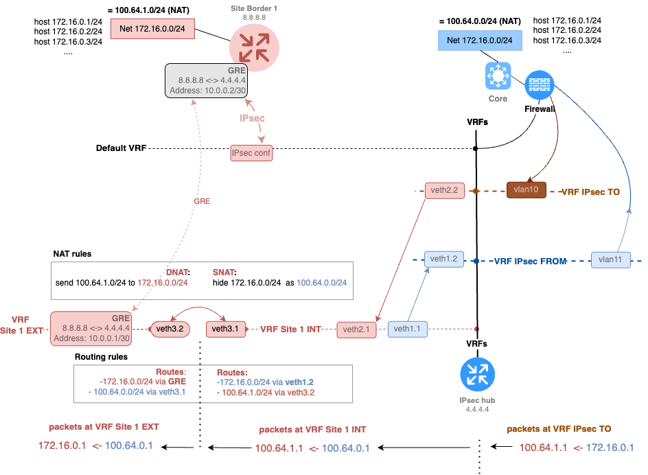
Netmap is a very flexible tool. With it, you can elegantly solve even the most complex interconnection scenarios.
Summary
Let's summarize this iteration of building our scheme. What requirements for our topology have we fulfilled today?
Traffic between branches should pass through a centralized firewall.Encrypted traffic between the data center and branches should pass through a centralized firewall.Tunnels should terminate on a single IPsec concentrator.The solution should be technically flexible and be able to terminate different types of tunnels in various configurations (VTI, GRE…).The solution should be flexibly managed.
We can say that today’s article was about manageability and flexibility. We showed that with the help of a concentrator, it is possible to solve a wide variety of tasks without using additional tools. We’ve added one more fulfilled requirement to our list. What remains?
The solution should not involve the firewall in dynamic routing.
The solution should be fault-tolerant.
The solution should not be proprietary.
The solution should support dynamic routing.
The solution should be scalable.
We’ll discuss solving these tasks in the following articles in the series.
Thank you for your attention, and see you next time!


Write comment