
- DIY
- A
Raccoon Flash Explorer | 9 months later…
Good night to everyone :)
9 months ago I released a BIOS programmer for computers and wrote an article about it.
At the time of publishing, it was pretty raw, and I only managed to realize all the initially announced features and bring it to a finished product just under a month ago.
Here I want to talk about how all of this happened, what difficulties there were, and random other stuff :)
Overall, there was a ton of material that, for various reasons, didn’t make it into the original article, but I’ll try to describe some moments here.
First of all, I’ll say that around autumn, at one of the most difficult times, when I had no idea how to solve a tricky coding task and was about to give up—the universe brought me together with an amazing person
Of course, this happened by chance, and in the very first minute of meeting we had a proper argument as you do, but a bit later when he learned more of the details, he gave high praise to my work and showed me his own projects. It was pretty unexpected, like meeting highly advanced aliens in a public, uh, forest, who don’t experiment on you but talk to you like good friends xD, and after this I started working on the project even more enthusiastically.
Overall, the project was appreciated only by tekkix regulars and a small group of repair techs. Many of them bought it just to play around—after all, we love collecting stuff, and you can never have too many gadgets :D—and only came to their conclusions about it after giving it a try in real tasks.
The main attitude of the target audience, who only heard about the project on YouTube or read about it on forums, was something like this:
-Oh, it’s just a regular USB stick on Arduino, lame, bring in the next one.
-It’s just a chxxx clone, nobody needs that.
-The author bought programmers in China and is just rebranding them.
-The author stole the firmware and hardware from an old xxx project.
-The author has no idea what programmers are and never even used them.
Unfortunately, the core part of the target audience turned out to be not ready for such innovations.
The final opinion is basically formed as soon as they hear "USB stick," and nobody looks into the technical specs or the capabilities offered.
That was our big mistake, as well as not paying enough attention in time to getting quality reviews from respected people in the repair field.
But it’s not all doom and gloom. Yesterday the thread describing the device was added to the list of pinned important topics on the main laptop repair forum, vlab.su, and I wrote a message there addressed to all the pros, and to the hardcore haters in particular.
Maybe this will help change how people feel about the project and things will go better, or maybe it won’t, and everything will be over soon. “We’ll see…”
Initially, nothing technical was planned here, and the article was going to be along the lines of "How we missed our startup." But as we all know, plans always change. Therefore, I’ve made a small description of various technical problems and their solutions, as far as my single brain could manage. I hope you’ll like it :)
I’ll say right away that I’m not a technical writer, I don’t have a specialized higher education, I’m a very beginner programmer, and I’m not good at presenting thoughts in a clear way. I’ll present it as it comes.
I'll keep the good slippers for myself, I’ll throw the bad-quality ones back)))
The example was taken from STC 65-USB-MSC_Mass Storage Class and significantly modified. The link is below.
Processor - 8051 STC8H8K64U.
I even bought a USB vid/pid. Officially, you can’t buy one code, but one of the old companies sells their stock. USB IF doesn’t get along with this vendor, but it can’t forbid or block it.
At the time I started coding, I knew about as much as "aaaa help me, the LED doesn't blink."
But I had enough experience in electronics, a desire to get a device, and an understanding of what it should be like.
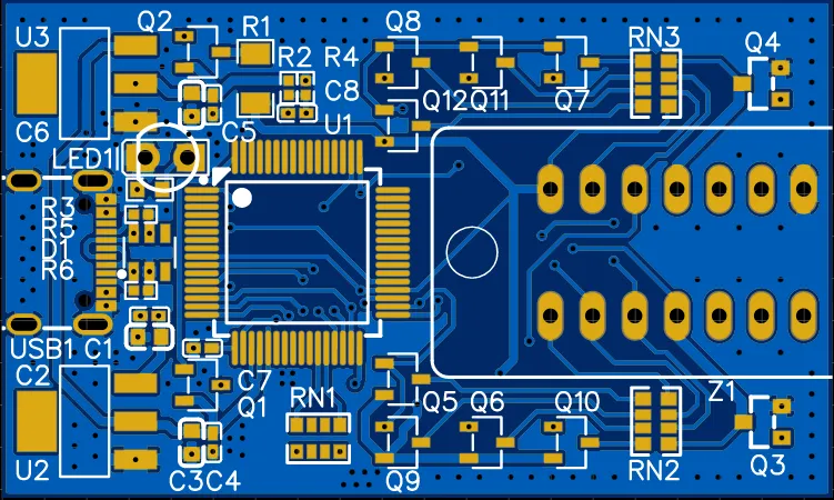
The hardware must be reliable. But it also should be simple and cheap. Which means there needs to be protection from overloads. But what’s the best way to implement it?

There was already a power switch for the socket (Q2), and the microcontroller had a fairly fast comparator with a switching time under 100ns.
Here’s what I ended up with. I used another special feature of the comparator’s design (mystery), and the circuit not only keeps track of overloads, but it can also compare parameters to a multi-point graph.
The comparator can track the direction of imbalance and rise time. It’s so sensitive that in pulse mode it can sniff out the current drawn by a single SPI flash chip. Because of this, I had to dampen its sensitivity a bit in software. The entire protection triggers within 2µs, so it’s basically impossible to fry anything.It had to support two power supplies from the start, 1.8V and 3.3V. Easy.
The microcontroller is powered from 3.3V, as are all its pins. But all the pins can be open drain.
So, I just hung an array of external pull-ups between the socket signal pins and the switchable supply, just in case, through separate switches. There was a mistake in the PCB layout here: one of the 8 switches is there just for symmetry and is shorted by traces. It was too late to redo the layout, and leaving the part off would look ugly. So it stayed in place)))No controls or indicators at all. But they’re needed. What to do?
There was simply nothing on the board for this. Adding wires everywhere would be a mess.
The board was made in a hurry, there wasn’t even a schematic at all beforehand.
Only a prototype with the microcontroller, a 3.3V regulator, and the socket, nothing else.
In a few hours, I came up with the whole programmer circuit on the fly, drew the PCB from it, and sent it for urgent production.
There was no way to even debug the drawn parts of the circuit before the boards arrived.
Building on a breadboard was problematic, and even the components were still in transit.
What if those sections needed to be redone? But no, that wouldn’t be fun))
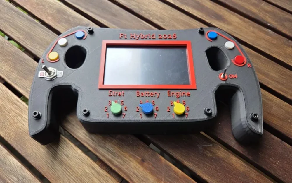
When laying out the PCB, I was primarily guided by the board’s appearance and size, since no enclosure was planned, and the device also had to look good.
Users developed various types of enclosures for us much later, for those who wanted to contribute to the project, and later one of those even became the default. But initially we didn’t plan any enclosures.
The optimal board size was needed to optimize the price, since they’re manufactured not one by one but as an entire panel.
Mounting a bare-board device had to be single-sided, to minimize knocked-off components underneath. Preferably easy for hand soldering too.
I spent most of the design time in the manufacturer’s online PCB price calculator.
Of course, there were no controls, protection, switchable pull-ups, or anything like that in the prototype or its software at the time. But the board was needed yesterday.There was a primitive flash detection using JEDEC ID, but it doesn’t really tell you anything. Many flash chips respond correctly even with the wrong supply voltage. There are plenty of parameters, and not all can be extracted from SFDP. A giant flash chip database just wouldn’t fit into the microcontroller’s 64kb code memory. Now what?
So I started digging through junk and looking for patterns in how flash chips behave depending on voltage. I searched for a long time. And hit the jackpot.
I can’t go into details, but I found about five behaviors that can be used to determine the required voltage for a flash chip with high accuracy.
Not 146% accuracy, but enough, since each subsequent test eliminates 90% of the previous error.
So I applied everything: ID checking, all the patterns, and contextual search for power-related entries in SFDP. The thing is: the place and even the presence of the power entry depends on the manufacturer, not JEDEC.
But these records have a strictly maintained format.
This turned out to be enough to determine the correct supply better than any human or database.
Thanks to this, the programmer also started being able to weed out bad flash chips or those with slightly off parameters. But this feature is still not deeply explored.Needs to be faster—no one wants to wait long.
Initially, I didn’t plan to speed things up at all, everything was chugging along at ~150kb/s as in the vendor’s example. I had no clue how to improve this, nor any programming skills.
Then I discovered assembler. Learned a bit about the registers, how USB works, and started coming up with my own ideas.
Tried many variations, every month something was redone as I learned more about writing programs.
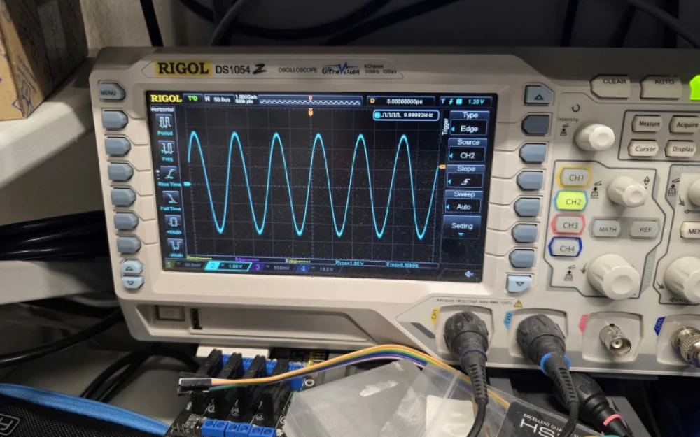
At some point, there was nothing left to improve—I hit the 750kb/s limit for this microcontroller. It just can’t go faster, because there’s no USB double buffering, no DMA, and every move with USB is through indirect addressing. But I wanted more speed.
SPI can run up to 22MHz, but because of the USB bottleneck, it just sits idle too much. But verification is needed as well. Until now, verification had to be manual, or time was wasted on automatic block-by-block checking.
Another headache was the giant 350ns+ pause between every SPI byte. These pauses existed even when using SPI-XRAM DMA. Setting priorities didn’t help, it’s a hardware limitation. I tried running with external clocking and got tons of data errors. DMA can’t work with XRAM uninterrupted.
Byte duration was 690ns and these pauses were a major annoyance. I had to ditch DMA entirely.
I poked around in the MCU, mapped SPI module timings, studied durations and dependencies for its commands (not in the datasheet), laid out some NOPs for precise sync with the SPI shift register state after program jumps, and got these nice timings.The significant speed gain allowed reading a 64-byte block from the flash twice while another 64-byte block flies over USB.
So, 8MB/~11s fits within ~750kb/s even with verification,
and verification stopped affecting read time. Write time is a different story, and you can’t escape the per-chip timings.
If someone says there’s no verification on the PC side—they’re not quite right. There is verification: hardware CRC-16 check. It’s part of USB bulk.Text files with all sorts of inside info about the plugged-in flash.
Just reading and writing dumps isn’t enough, you also need to see certain parameters.
All the information from the flash, including register contents and their modification, errors, contact state—all output to a text file.
The file is generated on the fly. There’s no other way.
At first, it was a bunch of if(a) strcpy("AAA"); else strcpy("BBB;), opened noticeably slow and ate a lot of RAM.
The first problem was solved by simply boosting the clock from 24 to 44MHz, and the lag seemed to go away. But the second problem remained, and had to be solved. Also, it was hard to add new messages—they took too much memory and too many lines of code.
For the first four months I didn’t know how to fix it, lacked the experience. But then I came up with something.
The MCU has a dual reverse auto-pointer for XRAM (Dual DPTR), meaning it can store two pointers, auto-increment/decrement after access, and switch between them based on how you set it up.
They’re almost independently configurable.
But no compiler can use them properly; it always uses the old-fashioned single one via INC DPTR.
I didn’t write my own asm strcpy or memcpy, but did something else instead. (Well, I wrote a special memcpy later, but for other tasks.)
I created the format for storing all text messages like this:Parameter names are stored as a block.
5 – Length of the block in sections, including the newline.
9 – Length of the parameter name in characters, then the name.
39 – Free space for the parameter value, after which comes the new line.
The required parameter block is copied to RAM by a fast assembler function that sees the length of each element as the first parameter.
Addresses in ROM and RAM are accessed sequentially, each has its own pointer, no jumping back and forth, so it’s copied as fast as possible.
Then a struct mask-pointer is applied, and the parameter values are copied into RAM from wherever we want in the code.The values look like this.
Nothing special. Also starts with the number of characters, then the array.The idea behind this way of structuring the text and the copying routines is that at the start you load the symbol/block counts into Rx registers, then just run a short loop like do{...}while(--Rx);. The file now gets generated and opened quickly even at 6-8MHz, whereas before it’d lag at 24MHz.
The dual pointers auto-increment/decrement and switch between each other as needed after every access. Their behavior is fully configurable. But compilers don’t know how to use this(((
This also makes it easy to hot-swap localization.
This feature isn’t there yet, but might show up. You’d just need to put a file with the same structure and your language on the disk, and the values will be loaded into memory from there.25Q64.
At first, I didn’t plan to identify all SPI flashes by their own names.
Just calling them 25Qxx was fine. But then it got boring.
I started thinking how to reliably work out the name and memory size without filling all of RAM with a database. Let’s just say I’m not a math person at all and don’t know the multiplication table even with a calculator, so I never got the “log-something” used to encode the size in the last byte of the ID.
Whatever. So I did my own implementation with bit shifts, quickly.I also made number generation for the last digits in the marking, which indicate size.
I left vendor codes in a table, it’s tiny and maps the first letters of the marking, but had to put in more work to guess the middle and last letters more accurately.
The thing is, for most flashes you can’t get the letters from the ID, and their meaning changes everywhere.
So... Some letters are determined by what working voltage I detected, others by the presence/absence of QPI/QUAD modes, and whether those can be turned on/off. Sometimes the mode’s fixed on and can’t be disabled.
Different chips have totally different patterns, so you can’t describe for each one.
You also can’t get the letters 146% accurately, only approximately.
But that’s fine, it’s just cosmetics)
If the name can’t be found, it’ll just show the JEDEC ID, and you can still work with it. And what if there’s a non-standard ID? Well... That’s bad, but not a disaster.
For ancient flashes there’s a table remapping IDs, but both those chips and their devices are rare as mammoths.
And anything released since 2011 always has SFDP which must include the size.SOIC clip.
Error checking and frequency selection for in-circuit work.
In-circuit was listed as a feature from the start, couldn’t let people down after all the earlier work, so after those issues above I focused on the clip.
There are several problems here at once:
1 – High current draw by the board.
2 – Interference from the board when it also wants to poke at the flash.
3 – Wires and speed. Need the maximum possible speed.
4 – Flash and voltage auto-detect. How not to apply 3.3V where it should be 1.8V.
Problems 1 and 4 solved themselves thanks to crazy overload protection in automatic mode for newbies, and by adding the option to turn off protection and manually set the voltage for advanced users.
Problem 2 basically worked itself out too, as much as could be without adding more parts.
The microcontroller has pretty beefy and rugged outputs. Also, the S51 family’s outputs are designed in a really interesting way: they can briefly or permanently go into push-pull mode.
It switches to stronger outputs only in manual mode, and sometimes can even override board interference. No boosting is needed for 1.8V most of the time.
In auto mode, just low-resistance pull-ups are used, which also helps.
If the microcontroller tries to override interference and can’t, it won’t burn the pins—it’ll mention in the log: can’t do it for this reason, desolder it.
Problem 3 was the most interesting. I spent a long time here, added loads of checks and retries for everything that could possibly be read at different clock speeds.
Eventually it worked 95% reliably. But I wanted 995%.
Later, while reading the "JEP106" spec on vendor codes (how first byte of ID maps to vendors), I noticed the codes aren’t really random—they have a parity check.
The high bit is a parity flag for the lower 7 bits. Quick nose-picking later, I added this parity check and got not 995%, but at least 146% accuracy.I think I told everything I could, but if I remember more I’ll add it.


The release of the demo version of the software had been planned for a long time. Here it is.
I hope by now you’ve already carefully read the whole article, and taking into account the mitigating circumstances described there, you won’t throw old shoes at me for the awful code(((
Although I’d probably throw a couple of shoes at myself for this now.
If I started the project from scratch today, I could make it much better.
But it is what it is. It works well enough, and there was no time to spend on it. There were more important tasks.
The most important part has been removed from the demo and replaced with stubs. In some places, I even wrote entirely new implementations, like SPI read and write. The full version has completely different code. The difference between this firmware and the example it’s based on is just like the demo and the main version differ.
By the time of release, I didn’t have time to make the whole project look nice, and you can see how my experience changed over time just by looking at the code.
Some of the most critical parts were completely rewritten in the latest update, while others (the ones that worked well) remained old or were only minimally changed for compatibility with the new ones.
This was the way to get a stable version out as quickly as possible, and then refine everything under the hood later. Because users are waiting, and they don’t care what’s inside, as long as it works well on the outside.
The hardest part wasn’t about creating a disk and dumping the flash drive as a file on it. The disk was already done.
The real challenge was making it fast, reliable, and as automated as possible.
Demo firmware with open source part of the project
Here lives a lot of text :)
This is my note to those who hate the project.
It’s not really addressed to the folks at tekkix, and you can skip it. But if you’re really bored — go ahead)
It was supposed to be the main text here, but I was persuaded to remove it and replace it with technical details. It actually turned out better this way :)
There are a LOT of letters and whining in there, better not open it :)


Write comment