- DIY
- A
How many robots can you bake in the kitchen?
Hello, tekkix!
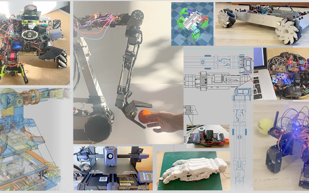
Fascinating DIY robotics.
PART ONE
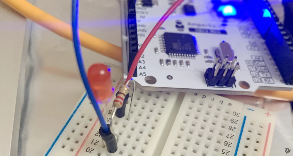
Once my friend gave me an Arduino kit for my birthday. I looked at the kit, said okay, thanks, and didn't touch it for six months. But it was the pandemic, already its second year, there was a lot of time, and I was lying on the couch with a laptop, I attached an LED to the Arduino pin (through a resistor, of course) and blinked it. Pff, damn, I thought, what nonsense, it's not clear why all this is needed...
But then over the course of a year, looking at sensors, motors, the simplicity of controlling all this, I somehow got involved. What struck me the most were servomotors. I connected three wires, wrote ten lines of code, and the motor cheerfully buzzed, setting the angle you specified. I remember how I connected the output of the ADXL345 gyroscope, its angle relative to the ground, to the angle of the servomotor. Without any PID (feedback control systems), just like this: motorAngle = centerMotorAngle + gyroscopeAngle. Structurally, there was one joint, the gyroscope was attached to the servo of the upper joint, and it "held" it level relative to the ground. Just rotating this structure, which quickly responded to the rotation of the lower joint, and rotating it back and forth, I thought, damn, that's cool.
And Ostap carried on...
JAD
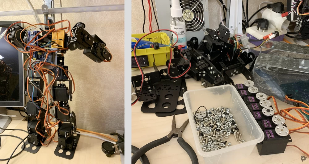
This stands for "Just another dog". At that time, only the lazy were not making robo-dogs. And I decided to make my own, of course. Based on my budget. Once, monitoring Avito for the words "servo, Arduino, and generally," I came across an interesting ad. Someone was trying to make such a "robot" entirely out of servos and U-shaped connections. I want to thank these kind people because, after some bargaining, I bought a bunch of servomotors and construction parts for their connection for 5,000 rubles. The robot looked like this (picture on the left), but after 15 minutes it looked like this (picture on the right).
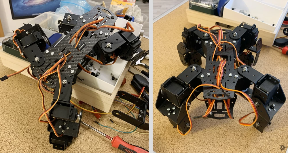
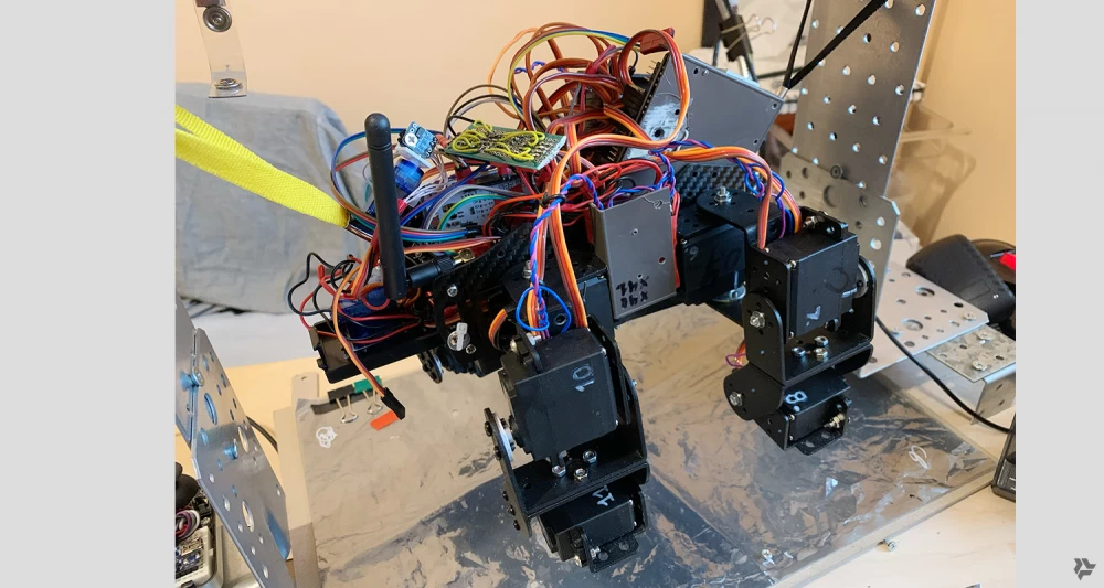
Since I understood that this was a completely non-working structure and it would never walk. And a bunch of servos will come in very handy. About the dog. I had to do everything on my knees and from improvised materials. For some time I was thinking about what to make the "body" of the dog from in order to attach the leg joints to it. Then I found a design for a quadcopter on the internet, it was two carbon plates with a bunch of holes. They were very light and strong. Using them and the stands for the quadcopter, I made a body inside which there was a compartment for 4x16850 batteries and a place for an Arduino with controllers for servos. The joints of the "legs" were made from this aluminum robot construction kit.
The dog is controlled by a remote control. It has two joysticks and a bunch of buttons. Throwing out everything that was in the remote control, I left only the joysticks, buttons and the case. I put an Arduino Nano, an RC (Radio controlled) module and a battery in there. The dog also has such a module. RC communication is very fast and in my apartment, for example, it works everywhere. You can't really transmit a lot of data there, but it's enough to control such a simple device.
At first, there were three joints in the legs. The last one was such a heel, which, as it turned out later, was not needed at all. It only added weight and consumed energy.
Details about the software
I wrote the control software based on the code found on the internet for controlling a hexapod, heavily reworking it.
Basically, you need to make a fairly simple walking cycle: three legs stand on the ground and they all move forward, moving the body, the fourth leg rises and takes a bigger step, then everything repeats with the other leg and so on in a cycle. Well, a couple of variations of gaits are also made depending on the needs.
To move right-left, that is, sideways, you need to place the leg that rises not forward, but to the side.
It was more difficult to make a smooth transition between forward-backward and right-left movements, so that the joystick could be smoothly controlled. But if you skillfully combine the cycles of lifting and lowering, then everything will work out.
At the same time, I was exploring physics simulators. I settled on MuJoCo, a lightweight 3D simulator in Python, which was later maintained by DeepMind. I inserted .STL models of motors and structures into it, described where everything is located, how it rotates, and made models of the leg and then the whole dog.
In the simulator, I worked on the gait and smoothness of transitions. An Arduino board connected to a laptop received signals from the remote control and sent data to a Python module, which changed the servo angles depending on the joystick positions. But not the real servos, but their models in the 3D simulator. This way, I managed to debug the control code without tormenting the dog in reality.
With such short legs, the dog walked very funny, more like minced. It quickly became clear that such a platform had no future. That is, it was pointless to make orientation in space, navigation, attach cameras, etc. Because the dog covered only a meter in a couple of minutes and staggered from side to side.
I wanted something faster, more mobile, and with more capabilities.
While working with servomotors, subtleties began to emerge that were not immediately visible. I realized that servo control is quite conditional. That is, you give the angle to which the servo shaft should turn. But at what point it actually turned to this angle is unknown. And the worst thing is that it is unknown in what position the shaft is when the servo is turned on. This is a very unpleasant moment, and I tried to solve it in various ways.
Details of servo control on PWM (pulse-width modulation)
Servomotors are controlled by a PWM signal.
The fact is that each servo consumes quite a lot of power, and when all 12 servos are running, the current consumption jumps to 9 amps or more. Although the batteries are powerful and can easily handle such a load, it is still a stress for the entire system, as the servos start at full power and their speed is not regulated, they can even pinch a finger.
When the dog is turned off, its "legs" can be moved to any position. When it is turned on, ideally each servo should report that it is in a certain position, and accordingly, the program would calculate the angle and speed and gently move the servos to some "average" position of the dog's legs, from which it could start any action. But the servos are cheap, they only have a control channel, and they do not transmit any data from themselves.
So this jerk of the whole dog at startup is terribly annoying, and it shows that you are not controlling the system, which is even more unpleasant.
After trying several options, I came up with a solution with a power delay line. Since the servos have a separate 6-volt power supply, it is easy to assemble a unit with a MOSFET transistor switch that will supply power to them, first with a delay until the AVR and PWM controller load and start working, and secondly, supply this power smoothly, gradually. This was done, which saved many of the dog's limbs and my fingers from being pinched. Then I also added that all 12 servos turn on sequentially, one after the other, which also reduced the load on the system.
A friend to whom I showed this video asked me: "How do you know which wire to connect where?" I thought. Indeed, how? And where? It's like asking an artist why he applied such a shade of color in this place on the canvas. By feeling.
Details about determining the actual position of the servo shaft
We do not know in what actual position the servo shaft is currently located during operation. I had to ask for help from the internet and it came. Inside each servo there is a potentiometer that is attached to its shaft and according to the readings of which the internal circuit of the servo works. We solder 1 wire to the central contact of this potentiometer. The ground is common, and it turns out that when the shaft moves, the potentiometer rotates and the voltage on the wire changes. We do not care what it is, it is important that it is proportional to the angle of rotation of the shaft. And this is what we need. Now the voltage on each servo is the angle of rotation in real time. So we do. We buy 4 three-channel voltmeters INA3221, connect one servo to each channel, 12 servos - 12 channels and voila, we have servos giving the angle. Well, you still need to select min max, correlate it with the angle, but these are details.
Dust
A friend's robot vacuum cleaner broke down and it went to me. Disassembling it, I found a lot of interesting things. After all, household appliances have developed quite a lot thanks to the progress of microelectronics. There was a main board, a board with a camera and a Wi-Fi module, a bunch of micro switches from different sides, IR sensors, a battery module, and of course the vacuum cleaner's filling.
The main control board was useless, as it was on the STM32 and performed its specific tasks. But the platform, with two motors that drove the wheels and a third wheel for balance, I drove for a while. I installed an Arduino with a motor driver on it and connected it to the same remote control, thus making a mobile platform. The accuracy of the movement was a problem, of course, since there were only two wheels. If they rotate equally, then we go forward or backward. If slightly differently, then we turn.
I tried to make the platform somehow feel the space. I tried IR sensors and TOF sensors. IR sensors are an LED and a photodiode in the infrared range, directed at an angle so that the reflection of the LED beam from the obstacle hits the photodiode. IR sensors did not work very confidently, at a short distance, somewhere up to 10-15 cm, and their work strongly depended on the surface in front of them, and they did not work at all in sunlight.
But TOF was more interesting. TOF is “Time of fly”. The sensor has a laser and a receiving module for the reflected beam. The sensor measures the time between the launch of the light beam and its arrival, thus calculating the distance to the point where it is directed. The sensor is relatively inexpensive and easily connects to the Arduino. But the problem is that it is narrowly directed, well, that is, it is a laser beam and, accordingly, it determines the distance only to the micro point where it is directed. I attached the sensor to a small structure that was evenly rotated by a servo. Thus, it turned out to be a radar that rotated in the plane and recorded the coordinates of the points in front of it in a buffer. This buffer was graphically displayed as a line, or a set of points, as a slice of space in front of the platform.
That is, the platform could already stop in front of obstacles and, by rotating the “radar”, find the space where it could go.
But this vacuum cleaner was very clumsy. I wanted something more agile.
OMNI
Once on the internet, I came across interesting wheels, a platform on which drove in any direction without turning the wheels at all. I found it interesting.
At that time, I no longer bought components and materials for my projects from Moscow companies. Once I looked at Aliexpress, I realized where happiness is. It was there that I bought my first Mecanum wheels and motors for them. While they were on their way, oh, it’s not fast, I made a platform for them.
The platform consisted of a carbon plate to which these motors were attached and on which everything else stood. 4 wheels, 4 motors and that's it.
Having studied the principles of control, I wrote the code. Here I wanted to do everything with a margin and for control I took the Arduino MEGA 2560 PRO controller. There on Aliexpress I also took the BMS board and 16850 batteries. BMS (Battery Management System) is a small controller board that manages the charge of each battery connected to it and also protects them from overcharging.
It all went something like this:
Details about the selection of PRM (motor revolutions per minute) of motors and about the parameters of motors in general
I did not know what speed motors were needed for such a platform. Therefore, I had to do everything by selection method. First, I took 300 revolutions, on them the platform started very slowly and heavily, but then accelerated very much, I didn't need that. I ordered new motors for 170 revolutions. These were better, although the acceleration was still long, tedious, with squeaking. The fact is that the motors are brushed, they start only with a certain voltage, that is, they have a gap, a step in control. Conditionally, when the driver gives them 8 volts, they still do not go but squeak. And when 9 they already spin, but not much. And then at 12 volts they are already driving at full speed. In short, somehow uneven. Well, it depends on the load, of course, on the weight of the platform itself.
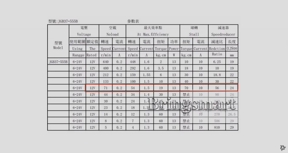
Brushed motors have 4 important parameters: shaft speed, torque, current consumption, and supply voltage. All these parameters are selected depending on the load. Therefore, competent manufacturers provide these parameters in tables, there are no-load values (No load), with nominal load (Nominal), and with such a load at which the motor stops, peak value (Stall).
For example, I give a table with the characteristics of the motor installed on my platform (it is in a red frame). As you can see, Chinese comrades produce a large range of motors, you can easily choose the right one.
For a specific task, you need to find the ratio of shaft speed to torque. And the power supply must provide the required current consumption.
The Mecanum wheel body that I purchased for the first time was plastic. Small rubberized rollers are fixed through plastic bushings. And when the platform moves, the wheels make such an unpleasant and rather loud noise. Probably this is the vibration of these plastic bushings. Of course, there was nothing about this in the description of the wheels, the effect is unpleasant, there is a lot of noise from the movement. And these rubberized rollers themselves are made of some very hard rubber, they are more likely plastic than rubber.
The reason I am so detailed is that, for example, it is unrealistic to make such a platform with voice control. When it moves, the noise is such that the microphones on the platform will not pick up anything except the wheels.
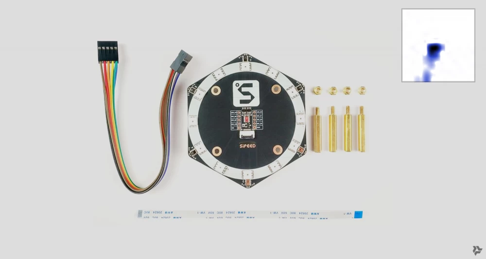
And I also have an omnidirectional microphone. Here it is, a fairly budget option.
This is a board with microphones directed in 6 directions and one in the center. This board is for determining the direction to the sound source. On the right in the picture is an example of the microphone output. It gives a 16x16 pixel bitmap with a “cloud” of directions to the sound source. In this case, it can be seen that the sounds come from somewhere in the south, southwest, and above, as the signal mainly hits the central microphone.
So you put it on the robot and it can determine from which direction the sound source is and somehow react, for example, turn to it. So with such a noise from plastic wheels, all microphones react to them. Although, to be fair, it is worth saying that when cheap servos rotate, the microphones also hear them.
SLAM problem
SLAM - (“Simultaneous localisation and mapping”).
Suppose the robot is turned on in some room, it needs to understand where it is, i.e., localize its position. If it has a map of the room, it needs to determine the point on the map where it is located. If it does not have a map, then it needs to build this map, and then determine the point where it is located. This is a double-edged sword or a chicken and egg problem.
This is a rather complex problem, many people are working on it and it is solved in different ways depending on the required accuracy of location data and the availability of environmental data.
A simple ready-made solution is data from GPS (only coordinates, without orientation).
However, GPS does not work well indoors and its accuracy sometimes varies greatly and is measured in meters (in the civilian range). This does not suit us.
For robots, one of the ways is VSLAM, which is localization by video stream (stereo video stream or even just by a single video stream) plus information from IMU sensors, accelerometers, gyroscopes, and magnetometers. (IMU - “Inertial measurement unit”).
For any SLAM methods, it would be good to verify the data by comparing them with reality. The data that is taken for verification, which is more or less accurate, is called Ground truth. Since I tried different SLAM methods, I had to make this system to verify the position of the robot in order to compare different SLAM systems.
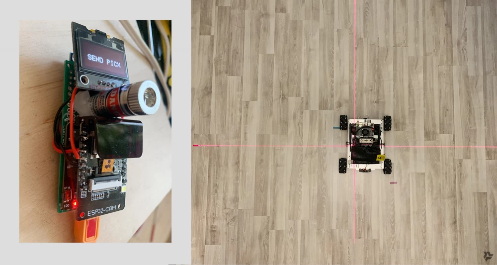
The Ground truth system I made is a camera (ESP32-CAM in my case) attached to the ceiling, covered with a bandpass IR filter and sending a video stream over Wi-Fi.
And three infrared LEDs mounted on the robot in a certain way. One LED in front of the platform, in the middle, and two at the back at the corners. The distance to the front LED should be greater than the distance between the corner, rear LEDs. The LEDs should be the highest and not be covered by any parts of the robot, they should shine upwards.
Details on how the system works. Calculation
The coordinate calculation system is simple, based on elementary trigonometry. In the frames received from the ceiling camera, top view, on a black background, only three points are visible (since the camera through the bandpass IR filter sees only LEDs emitting in the IR range). By the distance between the points, with fairly high accuracy (which depends on the resolution of the video stream and the diameter of the LEDs), it is possible to determine the coordinates of the center of the triangle formed by these three points in the coordinate system of the camera frame. This is the center of your robot x,y. In addition, since this is an isosceles triangle and its base is shorter than the sides, it is also possible to determine the platform rotation angle, which is also very important.
When the point moves, it shifts, and after the calculation, you get the coordinates of the center x,y and the rotation angle A. These are the Ground truth data with which you can compare the accuracy of different SLAM systems. In my room with a camera on the chandelier, this system "caught" the platform coordinates with fairly good accuracy in a space of about 2x3 meters (2x3 because the video camera frame is not square).
Lidar (Light Detection And Ranging)
On the "Pylia" project - a platform from a robot vacuum cleaner, I tried a simple radar on a TOF sensor, which rotated in a plane and produced a line of points, the distance to objects it was directed at. The measurement accuracy is not very high, the servo buzzes, and it does not rotate quickly. Therefore, I decided to buy a budget lidar.
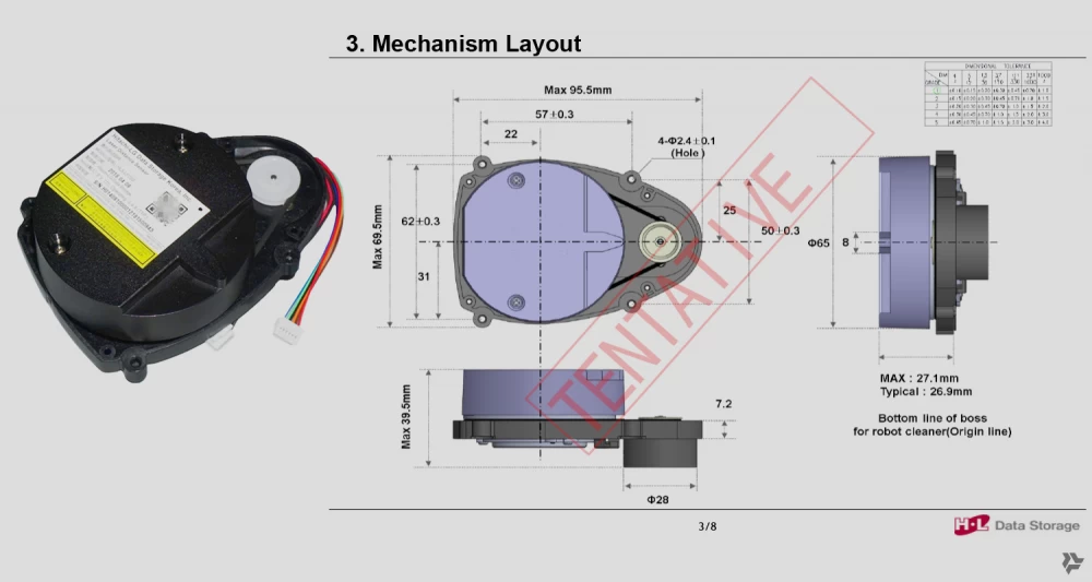
I found some offer on Aliexpress, checked if there were code examples for working with this lidar. I found the code, but in C. I bought the lidar for about 1200 rubles. I rewrote the code in C to Python because I needed it to work on Jetson Nano with my other Python modules. The lidar arrived, and after turning it on, it quickly output the angle, distance to the point where the beam hit, and the confidence parameter in the data correctness to the serial port. And so from 0 to 359 degrees, that is, in a circle. The model is, of course, cheap, some kind of non-standard or just an old model from a robot vacuum cleaner. Well, it works, okay.
Map. Lidar + Ground truth
Thus, I got the opportunity to obtain data for building a map of obstacles around the robot. Why data and not immediately a map, because a number of transformations still need to be done.
The lidar is mounted on the platform approximately in its geometric center. Graphically, the lidar data is an uneven line of points around the center. I decided to build the map quite rough. In order for it to work quickly and for me, in fact, I just need to see obstacles in real time in order to bypass them. Super millimeter accuracy is not needed here.
Details about building the map
Therefore, the space is divided into conditional cells, the size of which is half the size of the robot itself. So we got a grid. The robot is in the center. We overlaid the lidar data, these are just points around it for now. Next, we apply the Raycasting algorithm. It simply marks all the space located behind each lidar point as an obstacle, or as unknown. That is, if the lidar beam hits the leg of a chair, then beyond this leg it will no longer be able to "look", so we make a beam of a certain width from this point and mark all the cells on our map that fall into it with this beam.
Thus, some space around the robot is already emerging, somewhere closed and somewhere with gaps. We can move into these gaps.
In the video, the burgundy cells are where you can't go, the blue ones are slightly possible, the green ones are possible. Crosses are lidar data. The outline of the platform with wheels sometimes disappears and turns into a rectangle, there is no Grand truth data, the algorithm failed. The C-shaped obstacle on the left, where the robot is poking, is a movable obstacle (yoga mat), it easily moves it.
The advantage of having a map is also that we can poke a point in the space of this map and set this point as the target for the robot's movement. It seems so simple, but not everything is so obvious.
We choose a point on the map as a target. Since the robot knows its coordinates and angle of rotation relative to the zero of the map using Grand truth, it can determine the direction to the specified target and calculate the trajectory to it. It should turn towards it and go until its coordinates match the coordinates of the target. It's simple.
In theory, if SLAM works correctly, it should simply replace Grand truth and everything will work exactly the same. In theory. Serious people have been working on this for about 30 years.
Obstacle avoidance
We have a map with obstacles marked on it. We can give this map to an algorithm that searches for a path through the maze and thus solve the problem of obstacle avoidance. We look at different algorithms, take D* (pronounced D-star) for example. It only needs cells marked as obstacles, our position, and the position of the target as input. And that's it. We test it.
In the video, we click on any point on the map in real-time, this is the target where we need to go. The center is where we are going from. The lidar data is synthetic, just rotating in a circle, to test the algorithm so as not to run the lidar unnecessarily.
Then we break this path calculated by the algorithm into segments, and we travel along these short segments to our target point. In real-time, depending on the lidar data or our indication of a new target, everything is rebuilt and the route changes.
About SLAM itself
In my projects, I try to use software modules that are fast, lightweight, and preferably without a large number of dependencies. In Python or with a Python wrapper.
I have tried and am still trying to find SLAM software modules that could solve this problem on my equipment (2D lidar, IMU).
So far, I only find a bunch of modules for ROS and some snippets of code as proof of concept from scientific papers on SLAM, like FAST-SLAM 2.0 from ten years ago, all these Particle filter, Extended Kalman filter and Iterative Closest Point.
I have tried ROS, it does not suit me for a number of reasons mentioned above. So I will keep looking further.
By the way, a question for the experts. How do robot vacuum cleaners with a single 2D lidar, IMU, and maybe simple odometry build a map of a room in an apartment in a couple of minutes?
They build a map of the room, and then the entire apartment, and determine their location in it. So this is a solved SLAM problem. How do they do it? Do they run Unix and ROS? I don't believe it.
3D printer
The pandemic is over, I walked around, thought a lot, and one day I returned from the park fully convinced that I simply could not do without a 3D printer.
I had to make everything from improvised materials and foraged items. This greatly limits the possibilities of creating anything. It would seem, well, you take this thing, it is ready-made, combine it with this one and that's it. But how will it all hold together? Plastic? Metal? At home, in the kitchen? After watching YouTube videos, how they skillfully bake all these supports, mounts, cases, and other things on 3D printers, I realized it is my salvation, that I cannot do without it if I want to move forward. I am familiar with 3D modeling, I can make everything necessary in 3D.
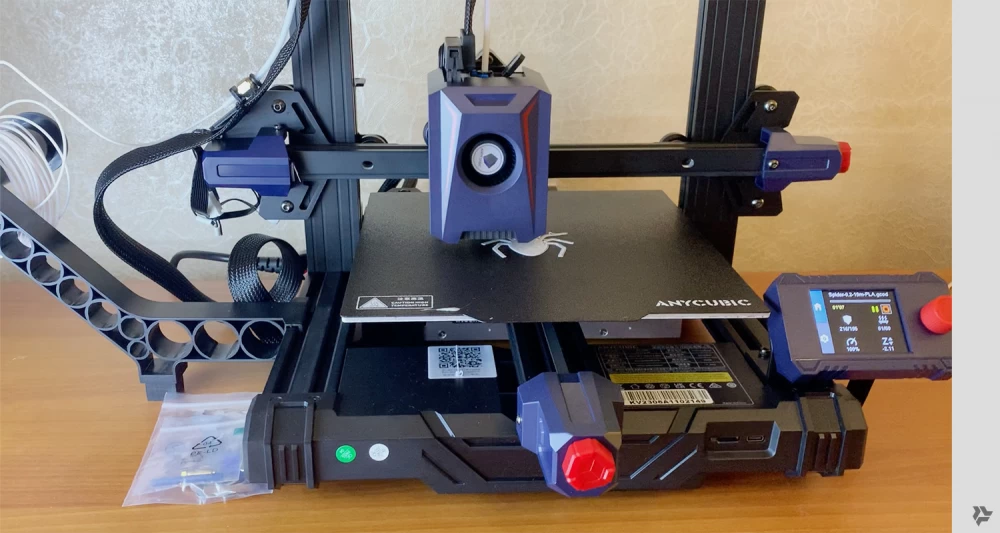
Again, I am, to put it mildly, not a very wealthy person. So I opened AliExpress and started looking at offers for 3D printers. I did not know a single brand, technology, or price. I thought that for less than a hundred thousand, you can't even get anything close. But it turned out that progress does not stand still. I immediately came across an offer for 15 thousand rubles. This is a kit that needs to be assembled from 5-7 parts, just by screwing them together. No problem.
I order. It arrives, turns out from a warehouse in Vnukovo, not even from China. But it took a week to get to Moscow, as if it came from China.
Ok. 40 minutes after I brought it from their pickup point, it was already assembled and working. It was printing something quickly with fast movements.
I was amazed. And a new era began.
The Era of Electronic Production
Yes, I understand that this is not a super printer, there are much better ones. But it prints. Not without problems, some of which I learned to deal with along the way. But it prints. 7 spools of PETG were used for printing, dozens of parts were made, 5 nozzles were clogged. A lot of waste with supports, test parts made of plastic, but that's ok.
The production technology has changed, or rather it has been organized. Everything needs to be done in 3D, that's obvious. To make some kind of block with batteries, you need to make 3D models of these batteries, the BMS board that is inside, all the mounting screws, all the holes for mounting, and empty spaces for the nuts that are then inserted into the plastic. Consider how this block will be printed, which side it will lie on the 3D printer table.
If these are structural parts that bear the load, you need to understand how the longitudinal/long plastic threads pass to ensure the necessary strength of the part.
If these are moving parts (I printed a couple of planetary gears as well as bearings and everything rotates), then you need to make the necessary clearances between the moving parts. To insert one part into another, you make a clearance of 0.1 or 0.2 mm between them. And the printer prints these 0.1 mm and the parts fit together.
When everything is done in 3D, there are many advantages. For example, you can immediately take some already made parts and use them in a 3D simulator. That's cool.
Gripper-Manipulator
As soon as I had the opportunity to make parts myself, I tried to make a gripper-manipulator based on servo motors.
These were still cheap servos with PWM control but already of two sizes, there were also small ones on which a grip could be made. Since there is no angle control in these servos, I had to come up with a way to stop when the object is captured. How to understand that the ball is already inside the grip. After searching for information, I found pressure sensors. They are miniature and change resistance from pressure and are easily connected to AVR. In the picture, they are under rubber pads.
SOC
For the robot to understand what to capture, it needs to "see" the target, for example, a ball. For this, I used the "Sipeed Maix Bit" board, which is a SOC, "System on a Chip", based on the K210 Kendryte. It is controlled by MicroPython, which is almost Python, a closed environment where you can only use what is available, or just standard, bare Python without libraries. There is something similar to CV2, simplified, but it works quite quickly. The Maix Bit also has a screen, which is convenient because it immediately displays the video that the camera captures, and you can draw your own information, text, graphics on top of it.
In this picture, you can see that the manipulator also has a TOF sensor, a rangefinder, and a second sensor APDS-9960 (this is a single-pixel camera, it determines the distance to the object also by TOF and also gives the color of the part of the object it sees).
This video shows an example of how to implement object tracking.
On the Maix Bit, video frames are captured from the camera. In this frame, using an analog of CV2, a part of the image with a certain color component (LAB color and so on) is found, then the position of this Blob (i.e., a bunch of pixels in the frame) is determined. And we get the coordinates of the center of the ball, let's say, in the coordinates of the video frame. These coordinates are sent to the PID motor control. If the ball is in the center, we stand still, if it shifts to the right, we move to the right, if it shifts to the left, we move to the left, and so on. This is how object tracking is implemented.
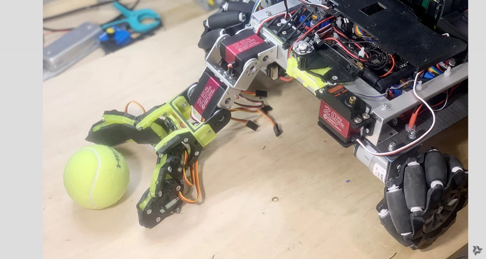
This is all in autonomous mode just like grabbing a ball. Using TOF, we determine that something is approaching the manipulator, if it is inside (distance of 5 cm, for example), we look at the color component through the APDS-9960, if there is a lot of yellow, then this is our tennis ball, we grab it. When the pressure sensors reach a certain resistance, we stop the gripping servos. This means the ball is inside the grip, we hold it.
Conclusion about the grip-manipulator. It will certainly hold a tennis ball, but it still turned out to be quite weak, since the final joints are held on the axis of small servos, and these are very thin structural elements and it will be difficult to hold something heavier with them. We need to change the idea.
Robo-finger prototype
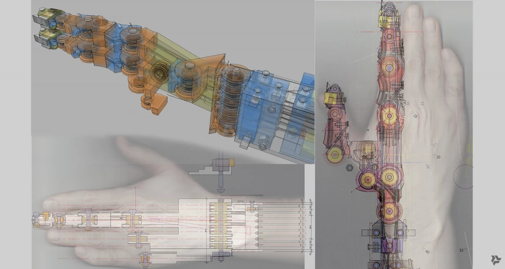
In movies and cartoons, I have long noticed different options for the hands of various robots and other mechanical characters. Everything looked convincing there. Well, the joints are the size of a human, bend in the same places, and the movements are therefore human-like. We need to try to make it, especially since I have my own 3D printer at hand, you only pay for the filament and electricity.
The idea arose that only cables that pull the joints and bearings should be placed in the fingers themselves for smooth rotation. And the cables themselves should be routed higher up the arm and pulled from there. This will also lighten the design of the hand itself.
Details about the construction of the fingers of the hand
Having tried different options for cables, I came to a twisted cable with a diameter of 1.2 mm, consisting of 9 strands of thin steel cables (found on Aliexpress). It is strong enough but at the same time flexible, as it needs to bend 90 degrees in the joints. There was a problem with processing the ends, when cutting they fluffed and it was difficult to work with them. Soldering with acid (F-38R is our everything) helped.
Each finger has three joints. I decided that in the index and middle fingers it is necessary to control the first phalanx separately, and the upper two will be controlled by one cable. The ring and little fingers, as they mainly perform holding functions, were also limited to one cable for all three joints. As a result, there were 8 cables in one direction and 8 in the other for the entire hand. That is, 16 cables led to 8 servos.
Additionally, the bending of the entire hand up and down was connected to a separate, powerful 25 kg servo, and the bending of the first phalanx of the thumb was also controlled by another 25 kg servo, as the thumb is opposed to all the others and bears a greater load when gripping. A total of 10 servos and 20 cables.
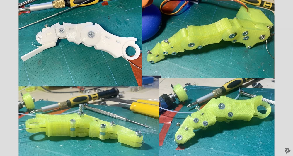
Inside each finger at the top there is a hole where the cable enters, then it is fixed at the end joint and exits along the bottom of the finger. In places where it will bend, polypropylene tubes are inserted, this is a very strong and slippery plastic, without it the cables would wear out the 3D printed part. As a result, when the finger is assembled, if you pull one end of the cable, the finger will bend, if you pull the other, it will straighten. This needs to be done simultaneously with tension, so to speak, otherwise there will be play and the finger will just dangle.
Therefore, a reliable system for attaching the cables to the servo axis was needed. This took some time, a lot of plastic was spent on prototype options. As a result, a large, thick washer with two edges for the cables was obtained, which was attached to the nylon cross of the servo, and cable mounts were made in it on M2.5 screws.
On the prototype, he seemed to grab everything quite briskly with one finger, if the object was rounded, he would wrap it around with his joints and hold it quite firmly. If it was a cubic object, he would hook onto the edge and the first phalanx would straighten. I thought that many fingers would enhance this effect. And I started making the whole hand.
But in the end, everything worked very poorly. I realized this when I finished all the fingers on the hand and tried to grab something. The fingers were dangling randomly, no precision, it was impossible to set the finger by all the joints, even with double control. The backlash was terrible, because if you hold the upper phalanges, the first ones just bent as they wanted, there are bearings and cables, all this moves freely... I don't know where I got so much perseverance to finish all this.
In short, two months of work down the drain.
Moreover, the hand, that is, the hand and the elbow joint turned out to be very heavy because I made the joint from an aluminum U-shaped channel, which itself weighed a lot, plus all the mounting plastic, servos and a bunch of screws and bearings. All this weighed about one and a half kilograms.
Epic fail. This hand, along with the servo-dog, is now in my personal Museum of Robotics 8) Although experience, even negative, is never superfluous.
OMNI V4
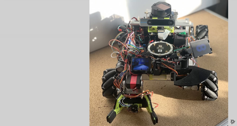
But new motors and Mecanum wheels came from Ali. The motors are more powerful, at 70 PRM. And the wheels with a metal structure. For this purpose, I also got more powerful motor drivers with brakes and idle. It was decided to make a new chassis a little larger, heavier and more massive. Since it was initially assumed that there would be a structure with a robotic arm on top.
The design is as simple and rigid as possible, 4 U-shaped aluminum channels 2 mm thick connected at the corners and another channel across, for rigidity.
In the corners, the motors are fastened with 3D printed plastic. It turned out to be quite strong.
The first riding tests went great. The wheel is metal, much more expensive than the first plastic ones, and under the weight of the entire platform, they behaved confidently and moved quite accurately and smoothly. The speed of the new platform is slightly lower than the old one, it does not accelerate as much. But this is not necessary, but rather accuracy and the ability to carry the load are important here, as the arm is on top and it needs to be balanced so that the entire platform does not tip over. However, the sound remained the same, it is a little softer, but it seems that it cannot be avoided with this type of wheel.
It was also necessary to significantly refine the power system. The motors on the new arm need 24 volts. And this is already a bank of 8 18650 batteries. And the second one for powering the chassis motors on 2x4 batteries, another 12 volts. Everything is connected to separate BMS and can be charged simply from an external charging unit without removing the batteries.
BLDC motors
BLDC are brushless motors that consist of a stator and a rotor. They are usually more powerful than brushed ones, much more efficient but also more difficult to control. They require a special controller. These motors are quite a recent invention and are very often used in robotics. All modern robot dogs have such motors, as well as humanoid robots.
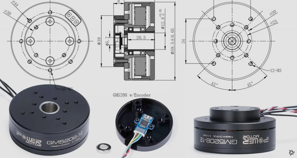
I started my acquaintance with BLDC motors with the iPower GM5208-12, an inexpensive so-called Gimbal motor, which is installed on camera gimbals. These gimbals are for quadcopters or handheld shooting. Usually, these are two or three such motors that, through a controller, allow for smoother shooting or holding the horizon, for example.
I bought it just to try and figure out how it works, as I had never dealt with this type of motor before.
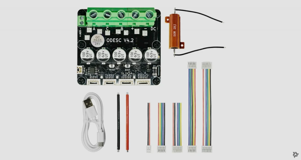
I also had to buy the ODESC V4.2 controller (Brushless Motor Controller), of course, on AliExpress. It turned out to be a rather interesting device.
It is controlled, or rather configured, by special software Odrivetool. There are probably a hundred parameters in the settings. It was very difficult to figure this out at first. But then when everything is set up, the motor is like an iPhone, it just works. You turn it on, set it to POSITION CONTROL mode, for example, and give it the angle to turn to, speed, and torque. And then the controller on the motor does all the work. It knows its position after turning on. And it just turns to the desired angle at the desired speed and, most importantly, holds that angle. The GM5208 is not a very powerful motor and can be moved by hand, with difficulty, but it immediately returns to the target position and holds it again. These motors also have a wheel mode, which is simply rotation in the desired direction at a certain speed and other modes. But for a robotic arm, for example, POSITION CONTROL mode is the most needed.
This motor also provides a lot of data about itself. Position, rotation speed, torque, temperature, current consumption, and much more. And all this at a tremendous speed and in real time.
All communication with this motor takes place via the CAN (CAN interface). This is a communication protocol for real-time end devices. It is quite simple, at first glance, broadcast, only two wires, transmits little data but very quickly.
Such motors usually do not have a shaft, the mount is made directly to the rotor on one side and to the stator on the other, making them much easier to mount, for example, on robotic joints.
These motors also come with built-in gearboxes. There can be a planetary gearbox or a harmonic drive. And it turns out that the rotor rotates the "input" of the gearbox and at its "output" there is a slower rotation of 10:1, for example, or 36:1, which greatly increases the torque and reduces the speed accordingly. This is ideal for robot joints.
Important point about BLDC motor encoders
A magnet is attached to the motor shaft or its rotating part. And a chip should be placed a couple of millimeters away, which detects the position of this magnet and determines the angle/position of the shaft with high accuracy (12 or 14 bits). This chip is the encoder, usually a Hall effect sensor is used there and a clever magnet with polarities not on the top and bottom but on the sides.
So, if the BLDC motor is without a gearbox and the encoder is on the shaft or rotor, then everything is fine, its controller knows exactly at what angle the shaft is turned at any moment.
But, if the motor has a gearbox, then the encoder should also be on the shaft/rotor and on the "output" shaft of the gearbox. That is, there should be two of them. The second one is called the "second encoder". The first encoder is needed for the motor controller itself to understand its position and control it. And the second encoder is more likely needed by the consumer of this motor, as its readings are the angle to which the joint has deviated. Although the motor controller also needs it, because when turned on, it must know the position of the "output" shaft/rotor of the gearbox to set the angle set by the user.
Sometimes BLDC motors with gearboxes come with two encoders, sometimes but not always. And this should be taken into account when purchasing. Otherwise, you will have to consider where to place the second encoder during the design process of the joint and then make the software and hardware control of the joint angle yourself.
This is the first part of the article. The second will be about the 6-DOF robotic arm, which is in the video below, about its assembly and control. As well as about the experience of working with an RGBD camera, which provides a depth map in addition to color. And about the nuances of working with Jetson Orin NX.
Write in the comments, share your experience in budget DIY robotics.




Write comment