- DIY
- A
Electrostatic Wind Generator
Historically, I have a weakness for generators of various types, and today we will consider another curious example, which implements a rather beautiful method of generating electricity — a bladeless wind generator.
Generally speaking, when you see the phrase “bladeless” and “wind generator,” it creates a kind of cognitive dissonance, as we are used to something completely different, and in our understanding, a wind generator is often represented as a huge structure with large blades...
However, as it turns out, such monstrous constructions are not at all necessary for generating electricity, and the generator can look (in its simplest form) like just, roughly speaking, a vertically installed stick and plate, without any blades! At the same time, any familiar mechanics performing some kind of motion are absent!
Before directly talking about the device itself, it should be noted that at the moment, such generators cannot compete in efficiency with their bladed counterparts, demonstrating an efficiency around 7% (for known samples), which, of course, cannot compete with the typical 45% of bladed wind turbines.
However, they demonstrate a very beautiful principle of generating electricity, showing in practice that a deep knowledge of physics allows one to create generators almost “out of a stick.”
Despite their apparent comparative inefficiency, in practical terms, the simplicity of their creation (and thus their low cost) is appealing, especially considering the widespread availability of low-power electronics today — various sensors, IoT device control components, which makes it worth taking a closer look at such interesting methods.
They also have their obvious advantages: the absence of mechanics, and thus no noise during operation, no wear and tear, and no negative impact on the environment (for example, on birds).
So, what is this device?
It is believed that the very first prototype of such a device was the generator proposed by the American Alvin Marks in 1977, who is considered the pioneer in creating such devices — in the specified year he received a patent for the system that is currently considered classical, consisting of two electrodes, one of which is called the emitter and the other the collector.
The emitter is represented by a pointed electrode or an array of electrodes, while the collector is a flat plate/net, etc. — that is, something with a relatively large surface area.
A high voltage is applied to the emitter, as a result of which charges start to fly out from the pointed* electrode of the emitter.
*It is the pointed electrode that coronates, as the highest electric field strength is observed at its tip.
It seems, at the moment, quite normal? However, Marks introduced the following innovations into this system: the collector is installed isolated from the ground, as a result of which charges begin to accumulate on it (the reason for their accumulation is explained below), while the emitter is connected to the ground and is not isolated.
Now, if you connect a useful load (some device of ours that requires power) between the collector and the ground, an electric current will arise.
But, "where is the generation?" — you may ask. "At the moment, we only see energy consumption!"
Here is the most interesting part: the inventor figured out that it is possible to increase the potential energy (read “start generating”) if work is done by overcoming the electric field force that hinders the movement of charged particles from the emitter to the collector!
The further explanation should be broken down into stages, as I also spent some time understanding how it works, because the principle of operation (in my opinion) is not particularly intuitive "right off the bat".
But, first, let's look at the picture, which shows the basic diagram of the entire system:
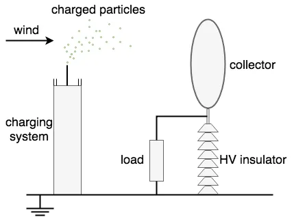
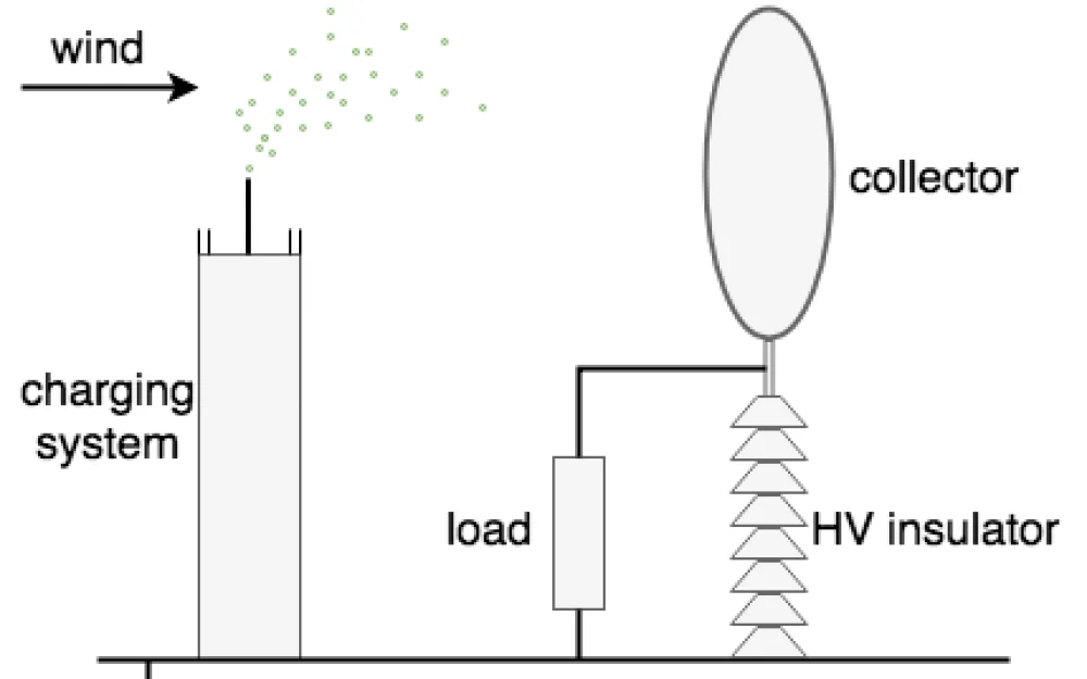
So, here we see the system described above, where the emitter (charging system) emits charges from the pointed electrode, which immediately start to blow toward the collector (collector) — by the wind (wind).
Since the collector is insulated (HV insulator) from the ground, it is initially electrically neutral and receives its charge of the same sign as the emitter, by receiving charged particles from it.
Now, it turns out that the collector has acquired a charge of the same sign as the emitter, as a result of which charges of the same sign start to repel each other.
And here, in fact, is the essence of the invention: Marx invented that the wind, which at the initial stage served for the primary charging of the collector, would later serve to do work, as if “against the force, driving charges” into the collector, transferring them to it!
In the common explanations of this moment, it is said that this can be figuratively compared to “lifting a stone up a mountain” — that is, performing some work while overcoming resistance.
Now, we see that the diagram also shows a load (load), which connects the collector and the ground — when such a load is connected, the charges begin to leak through it into the ground, and the potential of the collector begins to decrease, but the load is not a short circuit to the ground!
This means that charges leak through it at a certain rate, where for a certain period of time (if there were no influx of new charges), the amount of charge on the collector would equalize with the ground, and during this time the potential of the collector will continue to maintain the same sign as the emitter, gradually decreasing.
However, we constantly have a flow of new charges, and therefore, a certain potential of the same sign as the emitter continues to be maintained on the collector.
Achieving optimal system efficiency includes, at a minimum, selecting parameters such as: the collector area, the high voltage at the emitter, and the typical wind speed at that location.
In other words, roughly speaking, the charging voltage should be such that with the current wind strength, there is still no breakdown between the collector and emitter, (and again, with the current wind strength), it should still have enough power to overcome the repelling force of the charges at this voltage level and transfer the charges to the collector.
It immediately occurred to me, that in theory, an interesting generator of this type could be made if the entire setup (emitter and collector) was placed directly on a weathercock, freely rotating with the wind! :-)
Thus, it would be guaranteed that it would always be installed at the optimal angle to the incoming airflow, generating in the most efficient way.
Interestingly, such a design with two electrodes is not the only possible one, as shortly after the invention of the first design in 1977, Marx patented a second one (1982), which only required a single electrode:
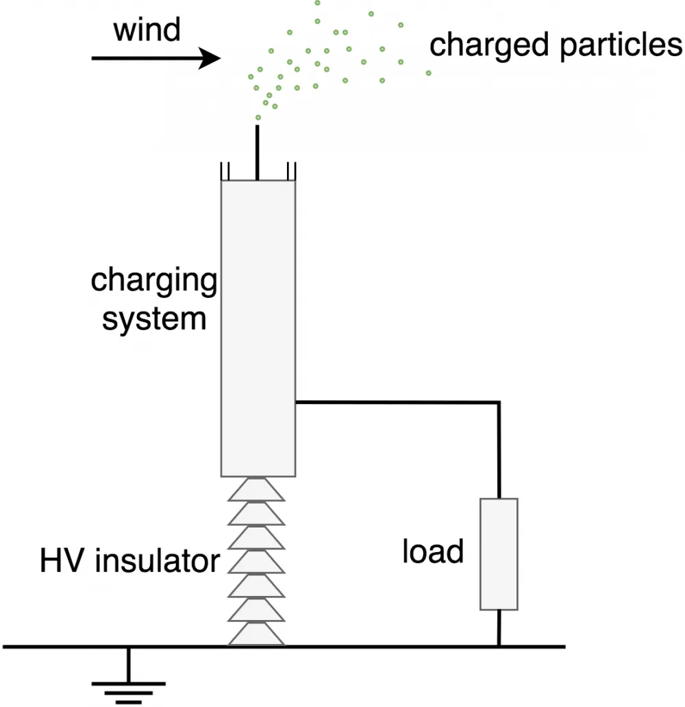
Here we see that one of the key elements is preserved, namely—the emitter, which still emits particles into the air, which, in turn, are blown away by the wind. Thus, the system constantly loses charges and a shortage of them starts to be observed— in other words, the emitter acquires polarity*.
*Here is another somewhat non-intuitive point, which is that despite the presence of polarity in the emitter — as a charge emitter, this is just a method of losing charges, while the emitter itself (as a device) is electrically neutral and only acquires polarity as it loses the charges emitted into the air.
I would compare this to an inflated balloon that is punctured, and air starts to blow out: as the air is released, the fullness of the balloon changes, and it shifts from "completely full" to "completely empty" (of course, this is somewhat exaggerated).
As a result, it becomes possible (as we can see in the image above) to connect a useful load (load) between the emitter and the ground.
Moreover, in the patent text itself* it is emphasized that the system simply will not work without water — this is a critically important element: the main means of charge loss by the emitter here is not the corona itself, but the spraying of charged microdroplets of water, sprayed through small holes.
It is also emphasized that the size of the holes critically affects the water consumption of the installation (one might even say the efficiency of the installation): with droplet diameters of 0.3 microns, the water consumption per hour will be about 10 gallons per m2, whereas if the droplet size is reduced to 0.03 microns, the consumption will drop to 0.01 gallons per hour, with the same output power per m2!
*About the patent text — as can be seen from the link above, the patent expired back in 2002, so, as they say, "hands are untied" :-)
More interestingly: in the patent text, it is shown that there are at least several installation options using solar energy, where the main role is played by the evaporation of water.
But the immediate question is, what does water have to do with this? The point here is that without water, the charges that have left the emitter will return to the ground at an unclear time and may "linger" in the air for a long time, while using sprayed water serves as a kind of ballast: the charges are carried not by air, but by water droplets, which fall to the ground fairly quickly under their own weight.
There is another very subtle point here, which is not explicitly stated, but is also quite important (as I understand it): in theory, even the wind is not necessary — we have done the work, lifted the water to a certain height, and after that, we spray it with a sprayer. It carries charges to the ground, generating electricity as a result.
That is, in this version, the water tank and the sprayer can act as a kind of water battery for electricity!
If the wind also gets involved in this process — it can carry water droplets a certain distance, and the greater that distance, the higher the potential difference!
So, in the version with the simple fall of the sprayed water (for example, if the system is installed indoors) — we get a water battery, whereas if the system is installed outdoors and the wind also affects it — we get a pure generator. Quite an interesting thing! :-)
You can correct me if someone understands this better:-)
Prototypes of such devices with a single electrode have been tested, and one of them is known under the name EWICON (Electrostatic WInd energy CONvertor) — you can read more about it at the link: as far as we can understand, it demonstrated the effectiveness of converting wind energy into electricity, around 7%.
It is noted that the technology is still in the process of improvement and therefore cannot yet compete with traditional methods of electricity generation, like wind turbines, but an obvious advantage of such installations (besides the ones already mentioned) is the ability to work in a very wide range of winds, whereas wind turbines are usually limited to a certain range, after which they can be destroyed.
Nevertheless, the simplicity of the generation principle itself and the potential low cost of such installations make them interesting for study, improvement, and possibly useful application...

Write comment