- DIY
- A
Homemade controller for Formula 1 racing wheel based on Raspberry Pi
I am a big fan of Formula 1, and since the races in Saudi Arabia and Bahrain were not included in the calendar at that point in the season, waiting for the next weekend seemed too long.
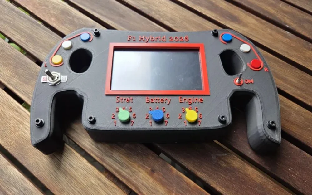
So instead of waiting impatiently, I decided to build my own controller in the form of a racing wheel to make the Formula 1 experience as immersive as possible at home.
The main component of the controller is a Raspberry Pi 5, which reads data from various switches and sensors and displays information on a 5-inch LCD screen. The controller works well with racing games, as left and right steering is controlled using an MPU-6050 accelerometer and gyroscope. It also includes vibration feedback for greater interactivity.
The controller has six tactile switches, two toggle switches, an accelerometer/gyroscope, a vibration motor, and three potentiometers. It can be used to play a variety of games.
The following sections explain step-by-step how to assemble the controller.
The tools and materials used in this project are listed below:
Raspberry Pi 5 (16 GB of RAM);
5-inch HDMI LCD display (XPT2046 touch controller — Waveshare);
Arduino Pro Micro;
Keystudio vibration motor;
Laptop for programming;
Soldering iron;
Solder;
Heat shrink tubing;
3D printer (Creality K2 Pro);
3D filament;
Double-sided adhesive tape;
Connecting wires;
0.25 mm winding wire;
Metal inserts;
Nuts and washers;
Diagonal cutters;
Screwdriver.
Step 1: Designing the controller case and 3D printing
The controller case design is based on the Mercedes F1 steering wheel. I used a photo of the steering wheel, imported it into Autodesk Inventor, and traced the case profile. Then I scaled the design so that the LCD screen fit neatly inside it.
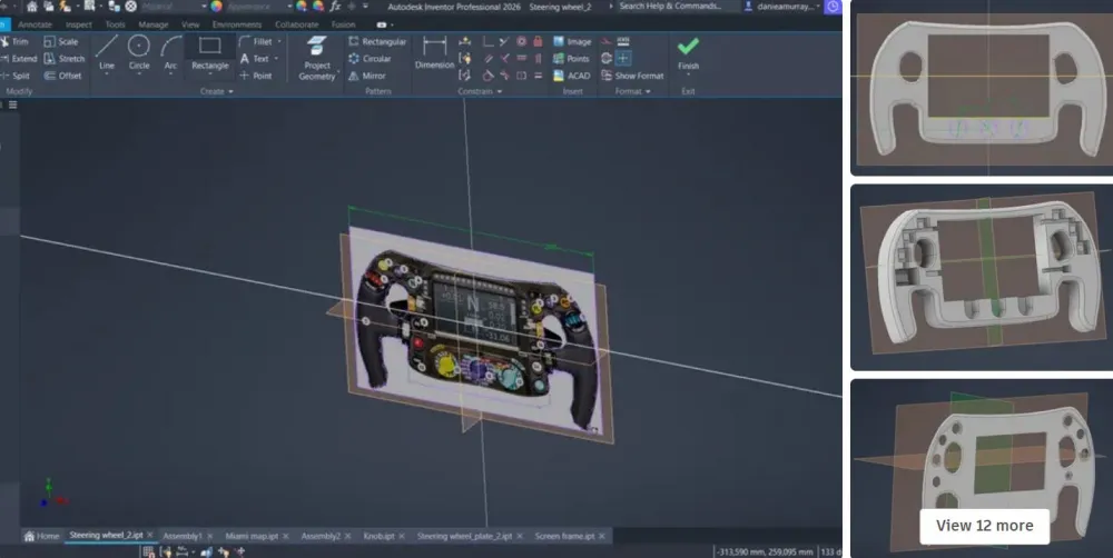
The case was designed so that all components fit exactly in their places, and this eliminated the need for additional supports. For neat wiring, grooves for each electronic component were also added. After completing work on the main case, a top plate was developed, and the text was added using slicing software for 3D printers Creality.
All electronics and wiring are located inside the case, and the top plate securely covers the components. Raspberry Pi is connected directly to the LCD screen via contact connectors, and the screen is attached to the back panel using standoffs. This back panel is attached to the back of the steering wheel, so the central hole remains open from both the front and back sides.
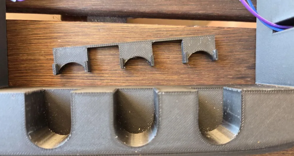
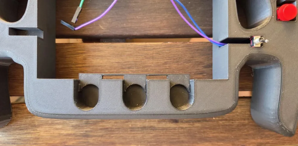
The next component designed in Inventor was a bracket for mounting potentiometers. Three potentiometers are located in the lower part of the steering wheel, and the bracket was designed for their reliable fixation.
After that I came up with special handles. They are mounted on the potentiometer shafts.
The final 3D model is a screen frame that surrounds the LCD screen, providing a neat appearance.
After completing all developments, the parts were printed on a 3D printer Creality K2 Pro. All components were made of PLA plastic, while the main case is made of PLA plastic imitating carbon fiber, and the rear panel is made of PLA plastic imitating wood.
Step 2: Adding electronics: Tactile and toggle switches
Electronic components include six tactile switches, two toggle switches, accelerometer/gyroscope, vibration motor and three potentiometers.
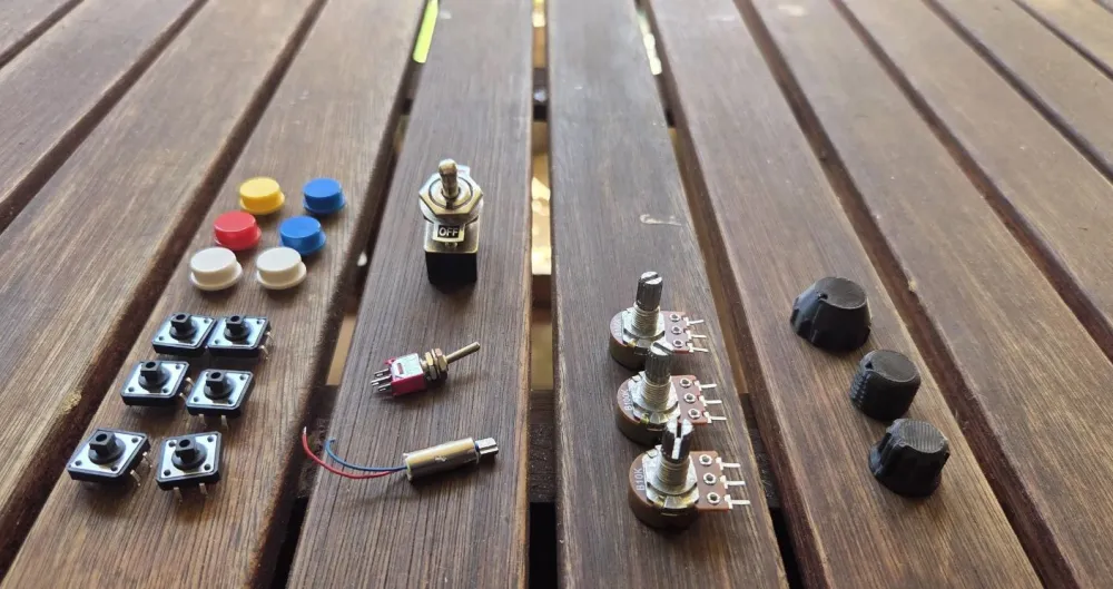
This section focuses on the added tactile and toggle switches. All eight are connected directly to the Raspberry Pi GPIO pins.

Tactile switches work in cycles—they close when pressed and open when released. Toggle switches are latching, so they stay in their position until manually switched back.
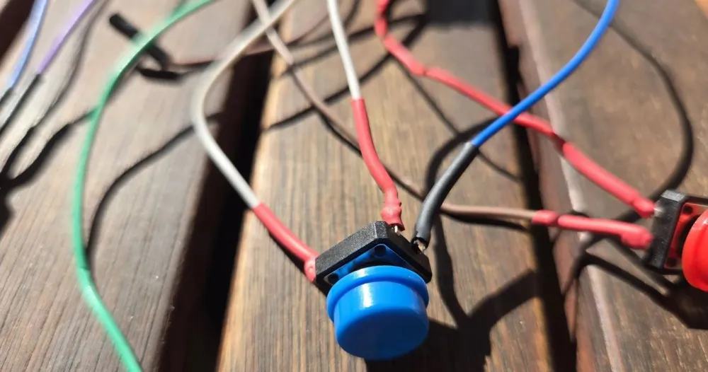
The following GPIO pins were used:
left blue: 20, left white: 13, yellow: 12, left toggle: 19, right blue: 5, right white: 6, red: 26, right toggle: 16.
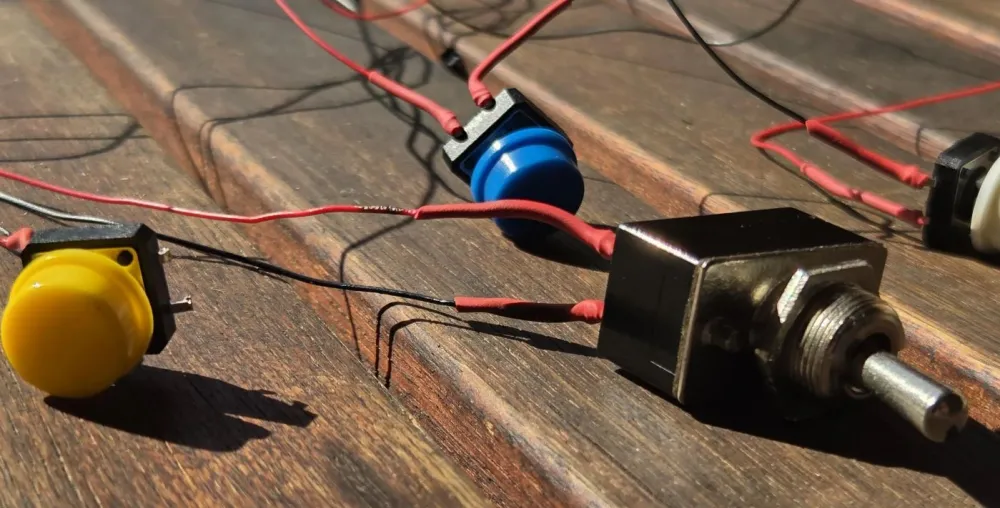
Each switch was connected as follows: one side of the switch to a GPIO pin, and the other to ground (GND). The Raspberry Pi's built-in pull-up resistors were enabled, so external ones were not required.
Initially I used standard jumper wires, but their thickness made it difficult to neatly route them inside the case. Then I switched to 0.25 mm² enamelled wire, which made the wiring much more compact and convenient. The wires were soldered to the switches and insulated with heat-shrink tubing.
Step 3: Adding electronics: Potentiometers
Potentiometers were added to simulate the rotary switches used on Formula 1 steering wheels. They are typically used to select items from a large list of options. For example, the strategy rotary switch on the Mercedes F1 steering wheel has options from 1 to 16, which are used to select preset engine settings for different race scenarios.
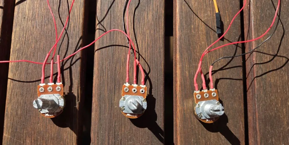
Three 10 kΩ potentiometers were used in this project. Reading analog signals turned out to be not so simple, since the Raspberry Pi has no built-in analog input capability. To solve this problem, I used an Arduino Pro Micro to read the three analog signals, and then transmitted the data to the Raspberry Pi via the UART protocol.
As a simpler solution, an ADC (analog-to-digital converter) chip could be used, but Arduino provides greater flexibility in processing and scaling analog signals when needed.
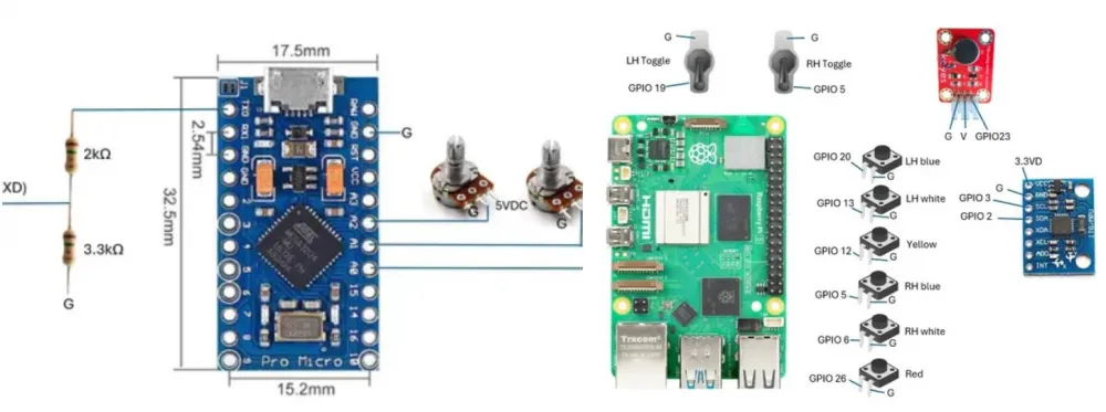
The potentiometers were powered from 5 V, and the slider outputs were connected to Arduino analog inputs A0, A1 and A2.
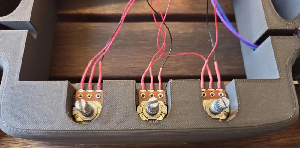
An important step was converting the Arduino TX output signal from 5 V logic level to the 3.3 V logic level required for the Raspberry Pi. This was implemented using a simple voltage divider consisting of 2 kOhm and 3.3 kOhm resistors.
Step 4: Adding electronics: MPU-6050 motion sensor
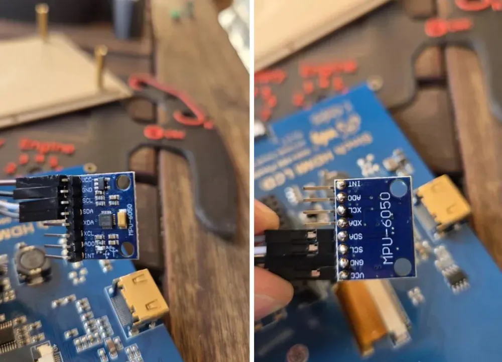
Sensors work excellently for determining the orientation of the steering wheel, and this makes racing gameplay much more realistic, allowing you to physically turn the wheel instead of pressing buttons to turn left or right. The device uses an accelerometer and gyroscope to determine tilt and rotation. The accelerometer measures tilt, which I used for left and right turns. The device transmits these measurements via the I2C protocol, which is connected directly to the Raspberry Pi's SDA and SCL pins. I used GPIO 2 (SDA) and GPIO 3 (SCL).
Step 5: Adding electronics: Vibration motor
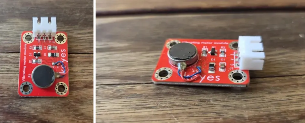
The vibration motor adds tactile feedback to the steering wheel and makes control feel more like using a real controller. This module can be used directly with the Raspberry Pi's GPIO pins. The board terminals are G, V and S, where G is ground, V is supply voltage (I used 5 V DC from the Raspberry Pi), and S is the signal, which I connected to a GPIO pin and which will turn on the motor when the voltage on the GPIO reaches 3.3 V DC.
Step 6: Adding electronics: Raspberry Pi and LCD display
The display makes the controller fully portable, so you can use it anywhere. It's also great that it's a touchscreen, so you don't need to remotely connect to the Raspberry Pi or use a mouse to open apps. Here is a link to the LCD display I used.
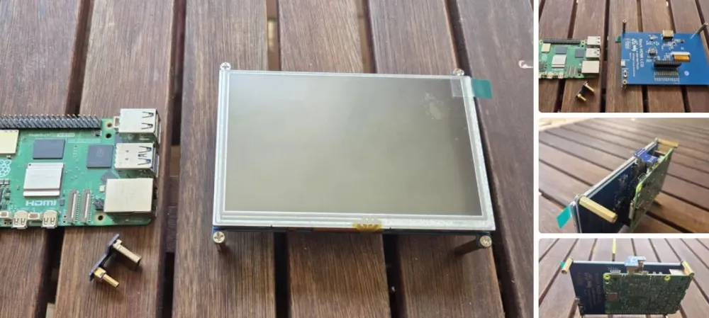
It connects directly to the Raspberry Pi's terminal block. The LCD screen connects to Pi pins 1 through 26, which is a bit inconvenient if you want to use those pins. In reality, the LCD display only uses 5 Pi pins, and the rest serve as additional support. I had to use some of those pins, but the LCD display has a terminal block connected to all the pins associated with the Raspberry Pi. I soldered wires directly to the terminal block, but I don't recommend doing that. It would be best to solder a pin header to these pins so you can connect jumpers. These headers are very small, and wires break easily when moving the LCD screen.
The LCD screen comes with an HDMI connector that plugs into the HDMI ports of the display and the Raspberry Pi. The display worked right away on my Pi 5, but the touchscreen didn't respond at first. I had to adjust some settings on the Pi before it started working. The link above will help with that.
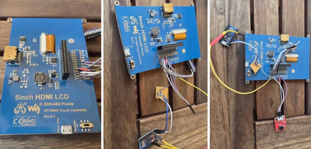
To connect to and program the Pi, I used remote connections via VNC. Just enter the Pi's IP address, and you will be able to remotely connect to the Pi's display.
Step 7: Wiring diagrams
This section shows the diagrams used to connect all components to the Pi. All G letters denote ground, and the grounds of the Arduino and Raspberry Pi must be connected. The connections have already been mentioned and listed in previous sections, and the attached images simply provide a clearer visual representation of all connections.
Step 8: Software
Raspberry Pi programming was carried out using Python, while Arduino programming was done using C++. This section explains what was implemented, and also provides all the code that was used.
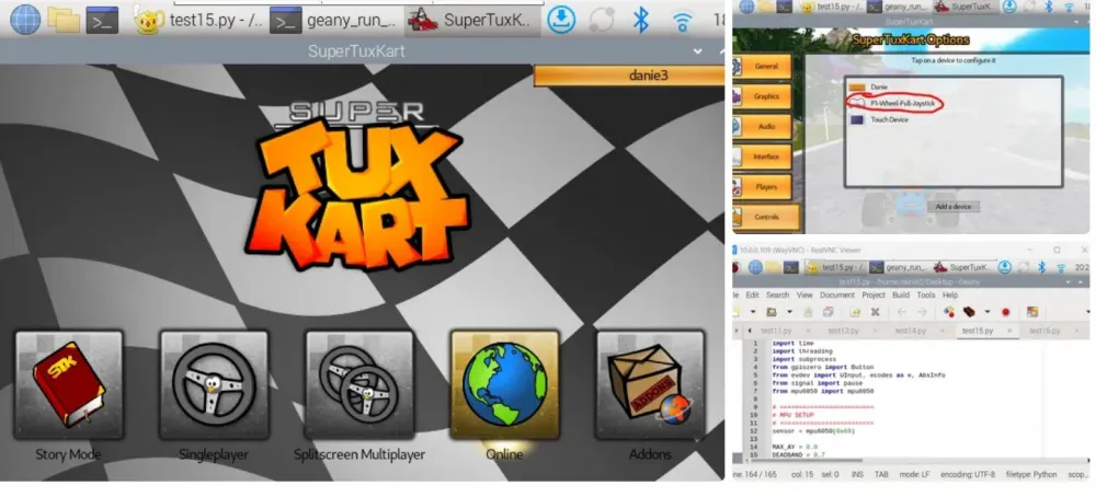
This controller can be used to play a wide variety of games, but I liked SuperTuxKart the most — it is an excellent racing game. I downloaded and installed the game on the Raspberry Pi, and programmed the Pi so that the game recognizes the controller as a joystick. When I launch the Python program, it immediately starts SuperTuxKart and configures all my components for use in the game. It is important that during control setup, the controller is recognized as a joystick.
I used Geany to run Python code.
The full working Python program is included, and the main part is explained below:
1. At the beginning of the code, several Python libraries are imported:
gpiozero is used to read physical buttons connected to the GPIO pins of the Raspberry Pi.
evdev is used to create virtual input devices, such as a joystick and a keyboard.
mpu6050 is used to read tilt data from the MPU-6050 sensor.
threading allows continuous reading of data from the motion sensor while the buttons continue to function.
subprocess is required to automatically launch SuperTuxKart from the script.
2. Setting up the MPU-6050 motion sensor
sensor = mpu6050(0x68)
The MPU-6050 is connected to the Raspberry Pi via I2C. Its default address is 0x68.
These settings are then used to configure the steering control:
MAX_AY defines what level of sensor movement corresponds to full steering wheel turn.
DEADBAND creates a small neutral zone around the center, so even the slightest vibrations do not affect the steering control.
SMOOTHING reduces jitter and makes the steering control smoother.
STEERING_DIRECTION is used to change the direction of the steering control if the left and right sides are swapped.
3. Creating a virtual joystick
The function joystick_capabilities creates a virtual joystick device.
This is exactly what allows SuperTuxKart to recognize a homemade steering wheel as a real gaming controller.
4. Creating a virtual keyboard for the menu
The joystick is used to control the car, but the menu is easier to control with a keyboard. Therefore, the program also creates a small virtual keyboard.
The keyboard_capabilities function does this:
Left white button → move left through the menu
Right white button → move right through the menu
Right blue button → Enter/Select
Left toggle button → Escape/Back
5. Assigning physical buttons
Each physical button is connected to a Raspberry Pi GPIO pin:
btn_red = Button(26, pull_up=True)
btn_yellow = Button(12, pull_up=True)
btn_left_white = Button(13, pull_up=True)
btn_right_white = Button(6, pull_up=True)
btn_left_blue = Button(20, pull_up=True)
btn_right_blue = Button(5, pull_up=True)
btn_left_toggle = Button(19, pull_up=True)
btn_right_toggle = Button(16, pull_up=True)
Button assignments:
Red button = GPIO 26 = Acceleration;
Yellow button = GPIO 12 = Brake / Reverse;
Left white = GPIO 13 = Menu left; Right white = GPIO 6 = Menu right;
Left blue = GPIO 20 = Nitro;
Right blue = GPIO 5 = Enter / Select;
Left toggle = GPIO 19 = Escape / Back;
Right toggle = GPIO 16 = Fire acceleration.
6. Mapping the MPU-6050 to analog steering control
def steering_loop(): Here, the program reads the Y-axis acceleration value from the MPU-6050.
def map_ay(ay): The sensor value is smoothed out, then converted to an X-axis joystick value.
This converts the sensor readings to the joystick range:
-32768 → fully left
0 → center
32767 → fully right
7. Running the control loop in the background
threading.Thread(target=steering_loop, daemon=True).start()
This allows continuous reading of data from the MPU-6050 while the rest of the program continues to respond to button presses. Without multithreading, the program would either read data from the sensor or from the buttons, but not both at the same time.
8. Automatic game launch
game = subprocess.Popen(["supertuxkart"])
This automatically launches SuperTuxKart when the controller management script is run. That is, I only need to run one Python file, and the game starts with the controller already active.
The full program is attached below.
The vibration motor and potentiometers are not used in this game, but they can be configured for another "Formula 1" simulator. Arduino is used to continuously transmit the analog values of the potentiometers, the C++ program is also attached. The program is simple: it simply reads the analog voltages from three potentiometers and continuously transmits data via UART from the Arduino TX pin to the Raspberry Pi RX pin.

Write comment