- Gadgets
- A
Crowbar circuit: reliable DIY protection for a 12V power circuit. How does it work?
Hello, tekkix! This is Anton Komarov, author of the special projects team at MTS Digital. Today I will tell you about an interesting DIY project that radio amateurs use to protect transceivers from voltage surges on the 12-volt line. It is called the Crowbar circuit: it acts just like a crowbar thrown on the terminals. It sounds unusual, of course, but it works!
How it all started
At one of the regular meetings of the radio amateur club, my acquaintance approached me with a request: to solder a protection circuit for a brand new HF transceiver. It is no secret that to achieve the minimum level of interference, such devices are powered by separate powerful power supplies. Alas, but even this will not protect the 12V line from high voltage by 100%. And if this happens, it will ensure an expensive device's journey to the afterlife.
To prevent such a scenario, an additional protection device can be connected between the transceiver and the power supply. The essence of it is to supply power directly in normal operation. If the voltage goes beyond the set limits, the circuit should not allow it to reach the input of the protected device.
It would seem, what could be easier than implementing this using a powerful transistor that will control the current flowing through it? On the one hand, yes, it will work. But only until the transistor breaks down between the collector and the emitter due to overvoltage. If it is higher than the stated characteristics, the element will fail. But this is not the worst thing.
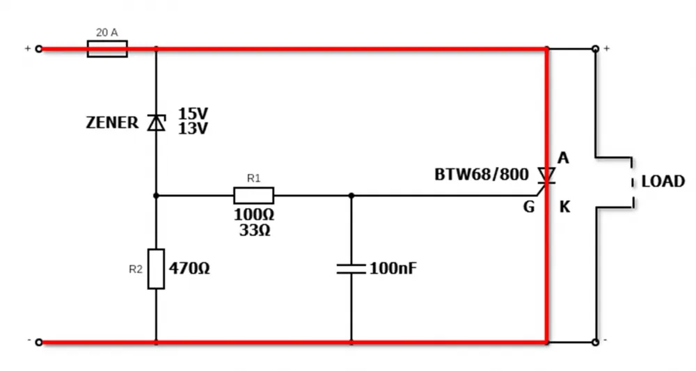
High voltage when the transistor breaks down will go further to the power input of the protected device with all the ensuing consequences. So you can take some other element, for example, a thyristor. For it, breakdown is a reversible phenomenon, and most importantly, it is its normal mode of operation. This feature allows you to implement a simple but very effective protection circuit:
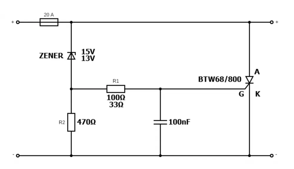
How the circuit works
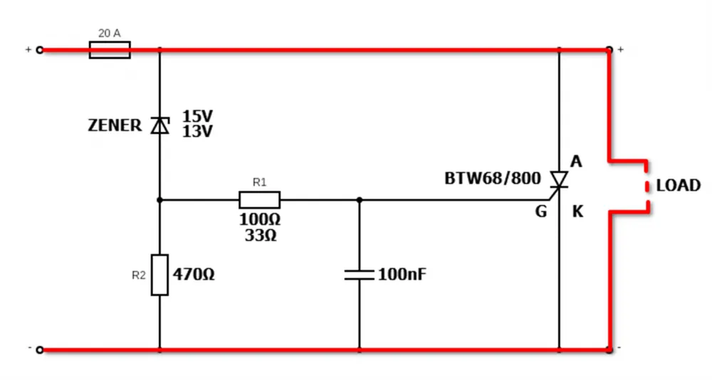
In the normal state, when the voltage from the power source does not exceed the breakdown voltage of the Zener diode, the BTW68/800 thyristor is closed. The current flows directly through the load:
But as soon as this condition is no longer met, the circuit will start working and various interesting processes will occur. First of all, the current overcomes the Zener diode and reaches the control contact of the thyristor (G). The resistance of resistor R2 is higher than R1, which limits the possibility of current flowing through it:
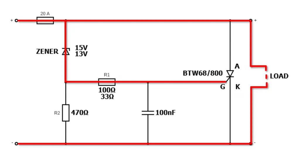
The thyristor opens and starts working in breakdown mode, effectively creating a short circuit in the circuit, as if a crowbar was thrown on the terminals. The peculiarity of this element is that when the voltage is removed from the control contact, it continues to operate in breakdown mode:
Now the only thing left is for the fuse to blow, breaking the electrical circuit:
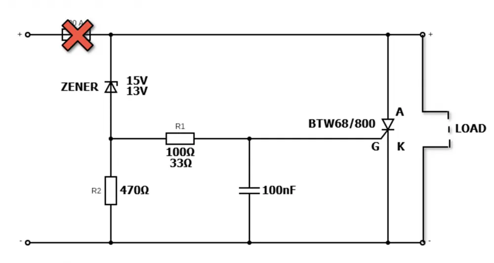
This will maintain the operability of the thyristor, allowing the protection circuit to be restored as soon as the fuse is replaced.
Practical Implementation
Theory is great, but when it comes to assembly, you need to think about which parts to order and how to make the device convenient to use. The first and most difficult task will be to find the required thyristor. I chose the BTW68/800 model:
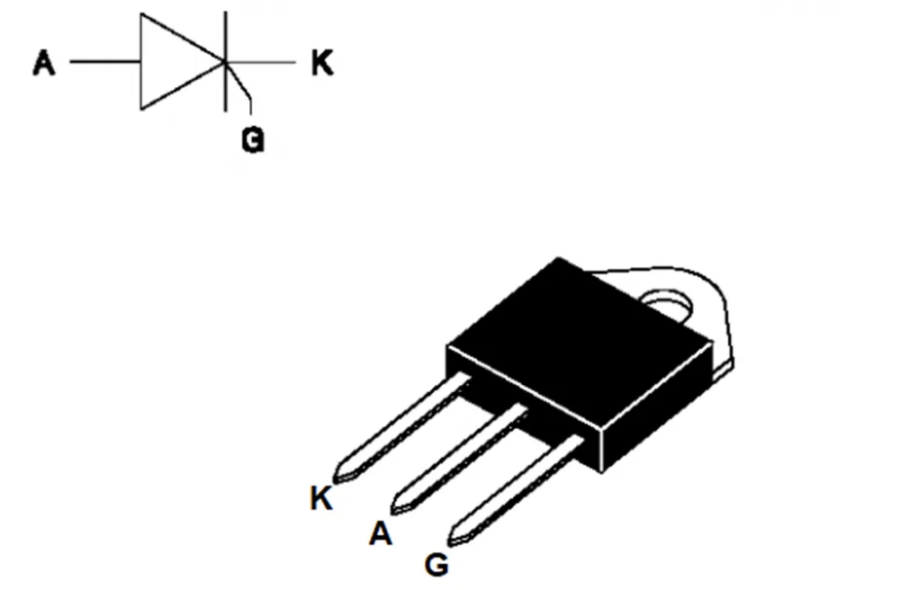
The numbers in its name mean the following:
maximum reverse voltage — 800 V. This is the value that can lead to uncontrolled breakdown of the element. In practice, it is unlikely to "arrive" on the 12 V line;
in normal breakdown mode, such a thyristor can "digest" a current of up to 68 A, provided proper cooling is ensured. In the finished protection device, it is not necessary to attach a radiator to it, since it simply will not have time to critically heat up before the fuse blows.
Here is the complete list of characteristics of the element from its datasheet:
Maximum average on-state current (Iᵀ(RMS)): 30 A.
Maximum reverse voltage: 800 V.
Holding current (Iₕ): not more than 75 mA.
Latching current (Iₗ): typically 40 mA.
Maximum surge on-state current (IᵀSM): 400 A (at pulse duration of 10 ms).
Forward voltage drop (VᵀM): 2.1 V (at 60 A current).
Critical rate of rise of current (dI/dt): 100 A/µs.
Critical rate of rise of voltage (dV/dt): 500 V/µs (at Vᵈʳᵐ = 800 V).
Operating junction temperature range (Tⱼ): from -40 to +125 °C.
Package type: TOP3.
Everything is great, the only downside can be considered the cost of the thyristor. In one of the most popular radio stores in Moscow, the price was $13.40 (at the time of writing this text). If you order from foreign marketplaces, it will be 30-40% cheaper even with delivery. As a Zener diode, I chose the popular 1N4744A.
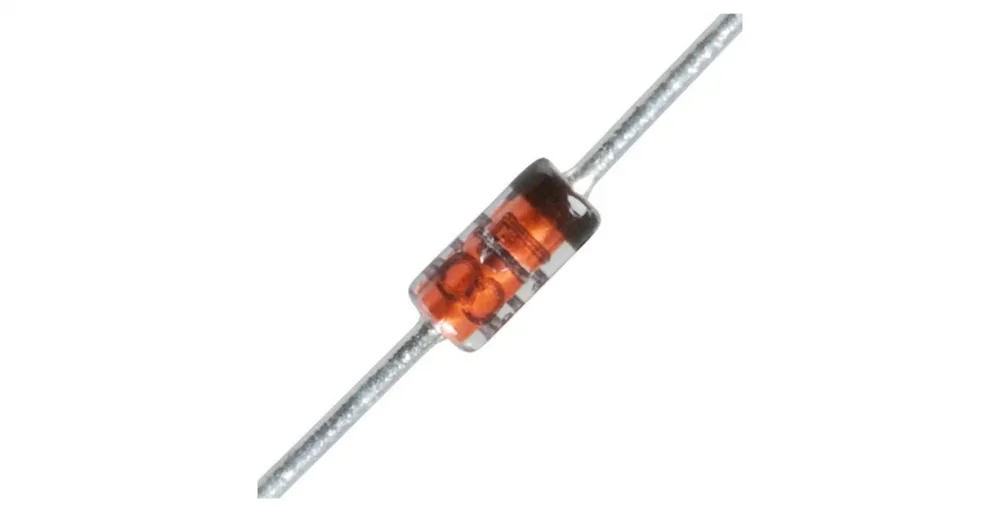
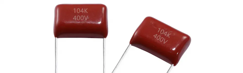
This diode costs about $0.05 and is available almost everywhere. As for the capacitor, I chose the simplest film one with the marking 104K 400V at 100nF. It cost me $0.21:
As for the resistors, I had them in stock, I bought a large set a long time ago. They also cost inexpensively, within $0.05 each. Now, however, an unnamed but well-known store sells them for $0.09. I also decided to make the potential replacement of the fuse convenient, so I looked into the nearest auto parts store and bought a holder for blade fuses, costing about $0.97.
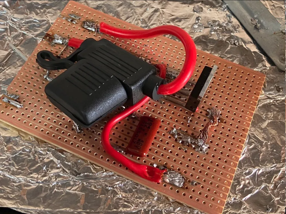
In the end, I collected all the details and went to a friend for final layout... But his soldering iron burned out and only his grandfather's (literally) was left, naturally, without any temperature control. And the tip there is almost as thick as a finger. The prototype looked like this:
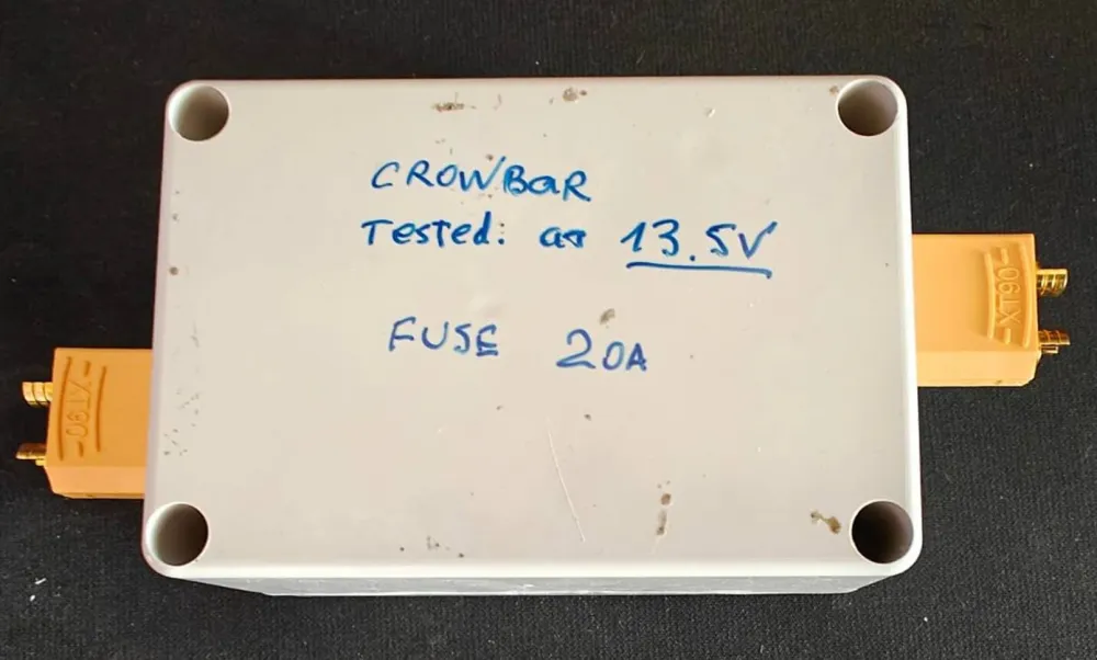
The soldering is terrible, of course, but the prototype worked immediately and without any complaints. Later, we reassembled everything together and packed it in a sealed case for REA ($3.40). Input and output are on XT90 connectors ($3.88), which are most often used for RC models. This is also a kind of protection against reverse polarity, because it can only be connected with the correct polarity.
I also have a photo of the finished and tested device:
I liked the Crowbar circuit primarily for its simplicity and utility. Nothing superfluous, and at the same time, the circuit can be assembled even by a person who has just learned to solder (the layout above looks about like that). Together with the order of the thyristor from the marketplace, such a homemade device cost about $18.45, which looks quite budget-friendly these days. Now it protects the HF transceiver, which costs two orders of magnitude higher.
How do you like the homemade product? Share your experience in the comments.


Write comment