- Network
- A
IPsecHub+. High Availability and Dynamic Routing
Hello everyone! Nikolay Edomsky here, Head of the Network Engineering Group at EDINOM TSUPIS.
I present to your attention the fifth article in the series "IPsecHub+".
In the previous articles, we explored various functions of our IPsec concentrator. However, one important question was left out, which is crucial for any serious topology — the question of fault tolerance. In this article, we will explore ways to make our concentrator fault-tolerant.
Dynamic Routing
Now, what kind of fault tolerance would be complete without dynamic routing, you might ask. And you would be right. In all the previous examples, we have considered the use of only static routes. Naturally, in an enterprise setting, such a configuration is unfeasible — I think it’s unnecessary to elaborate on why dynamic routing should still be implemented.
Implementing any dynamic routing protocol on our IPsec concentrator will be straightforward, as the topology is based on full-fledged logical interfaces — GRE, VTI, veth, and VLAN. I suggest considering the implementation of the BGP protocol on the concentrator, as this protocol will provide the most flexible configuration.
All we need to do is assign an autonomous system to each of our VRFs and create a BGP connection between all participating interfaces.
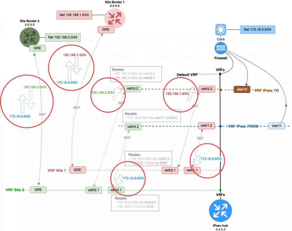
Here’s how it will look:
The diagram shows that we have connected all the nodes along the traffic path with BGP peering. The general concept of dynamic routing is as follows:
ipsecFROM sends the DC routes to the target VRFs of the branches
ipsecTO receives branch routes from their target VRFs.
The DC routes reach the branches via GRE from the target VRF.
The firewall still acts as an inter-VRF router.
The direction of prefix distribution is shown in the diagram with arrows. Additionally, each VRF should be assigned a separate AS, which will help avoid many issues related to AS loop and confusion with AD, as iBGP and eBGP have different AD values.
And most importantly — always remember the key rules of dynamic routing in an escalator topology.
Escalators to the branches only push traffic to the specific branch and nowhere else.
Escalators in the DC only lift traffic to the firewall and nowhere else.
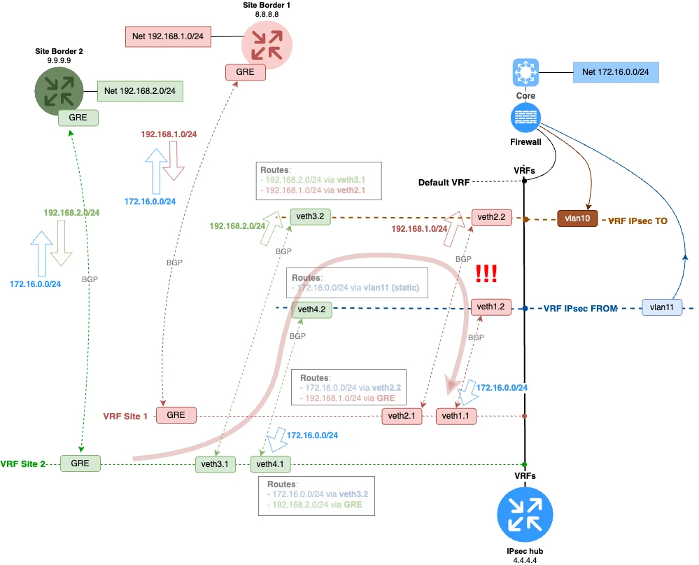
It is crucial to be very strict about which prefixes you send and receive on ipsecTO and ipsecFROM. The entire scheme could break if, for example, you send branch routes on ipsecFROM. The direction of distribution should be strictly as shown in the diagram below. We send the branch prefixes via ipsecTO, and the DC prefixes via ipsecFROM.
The situation shown in the image below is unacceptable. A route from the green branch VRF through VRF ipsecFROM leaks into the red branch VRF. In this case, traffic between the branches on the specified path will not be returned to the firewall. This would ruin the scheme, as it would create asymmetric traffic passing through the firewall.
Fault Tolerance
After we implemented BGP on our concentrator, we can discuss the basic fault tolerance of our solution. Fault tolerance will mainly consist of hardware redundancy for our concentrators.
We will discuss redundancy at the branches a little later.
What are the main tasks of redundancy?
We need to provide redundancy for the traffic acceptance point from the firewall. Since the firewall operates only with static routing, we need to present it with a point that will always be able to handle traffic to the branches. In the simplest case, this could be a VRRP domain (floating IP address).
We need to provide redundancy for the traffic acceptance point from the branches. For this, on the branch router, we add an additional GRE tunnel to the second data center IPsec concentrator.
Let’s place another IPsec concentrator and integrate it into our topology. It will be enough to clone the configuration of the already existing environment. The only changes needed will be the external address of the concentrator where the IPsec tunnel terminates, and the endpoints of the GRE tunnel with the corresponding GRE interface addresses. The veth interface addresses can remain unchanged, since they are not involved in interacting with hosts outside the internal loop of the concentrator.
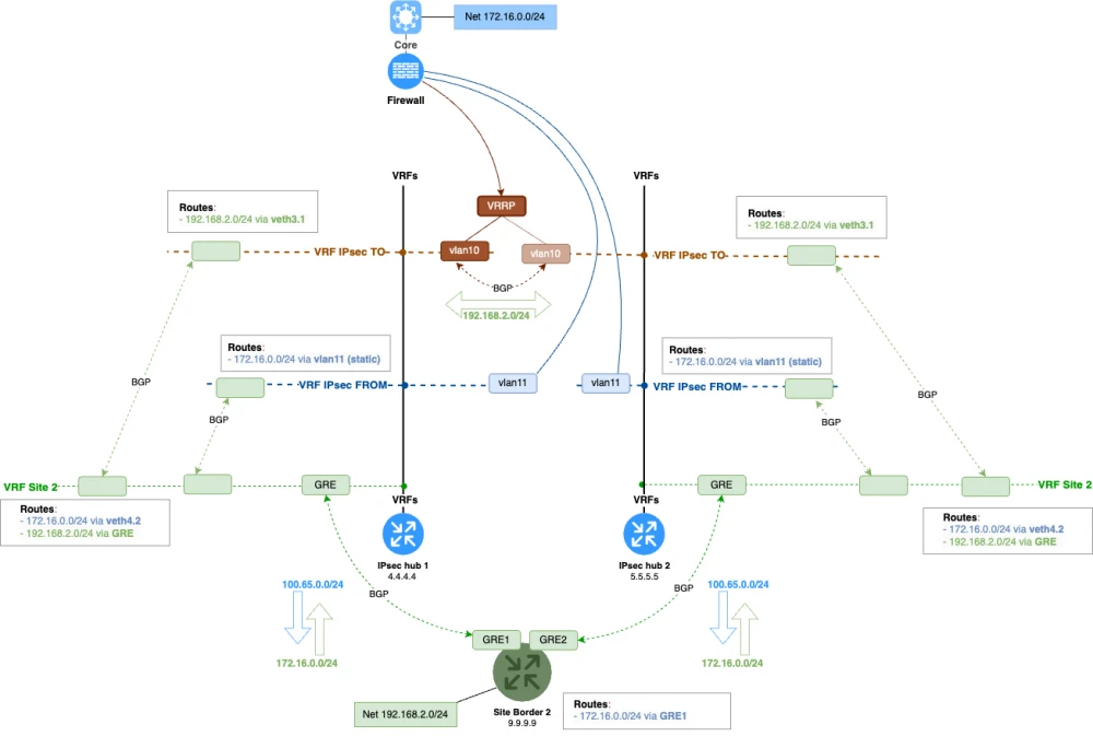
Let’s see what this scheme would look like. Dear readers, please click on the image for more comfortable viewing, as we are already dealing with extremely complex scenarios, and the schematics for such scenarios, unfortunately, turn out to be quite cumbersome.
We see that in the ipsecTO VRF we have organized a simple VRRP domain with a floating address. The static route to branch networks on the firewall will point to this address.
BGP peering in ipsecTO.
There is a very important point in such a configuration. Note that we also established BGP peering between the interfaces of the IPsec concentrators in the ipsecTO VRF. Why was this done?
If the IPsec concentrator loses the IPsec tunnel to a branch while being the VRRP master, it will not be able to route packets going to the branch, since it will no longer receive routes through the GRE tunnel. To prevent this, we established BGP peering between both IPsec concentrators. If at least one tunnel to a branch is operational, packets will be routed correctly. The VRRP master will receive the route to the branch through the neighboring IPsec concentrator if its own tunnel fails for any reason.
Fault tolerance and NAT
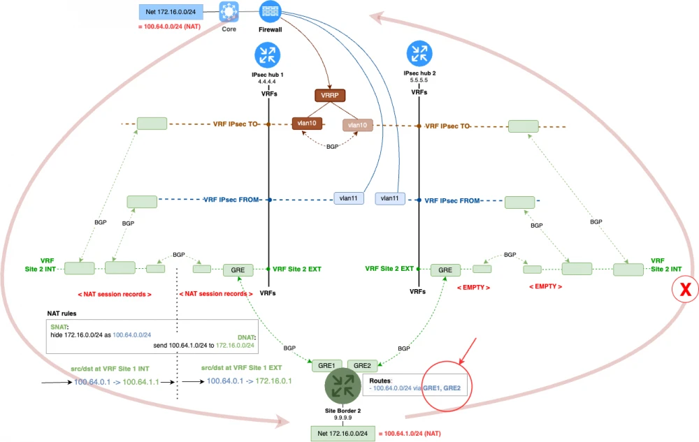
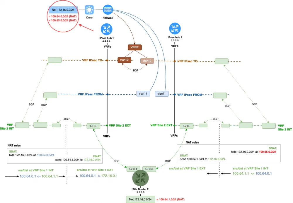
The topology becomes much more complex if we are providing redundancy for schemes involving NAT. The main issue is that when there is an alternate route to the data center and to the branches, there is a risk of requests going through one IPsec concentrator and responses coming back through another. An example of such a request can be seen in the diagram below.
Since the NAT record will only be created on the hub that receives the request, we must also route the response through it. This can be done in different ways, but the most reliable approach is as follows.
Terminate requests on one IPsec hub with one network, and on the other IPsec hub with another.
We add a new surrogate network, which will be used to terminate connections from the data center through the second hub—100.65.0.0/24. We configure the corresponding NAT rules on the second IPsec hub:
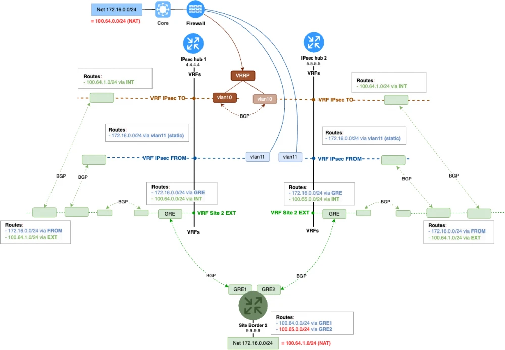
The configuration for routes in the overall scheme will be as follows. The main thing is to ensure the correct traffic direction to the surrogate replacement prefixes.
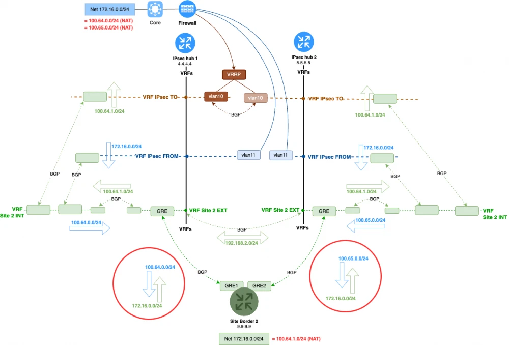
The dynamic routing configuration for the NAT scheme will look like this. We will need to send the corresponding covering networks to the branch from each hub.
Summary
Let’s sum up this iteration of building our scheme. Which requirements for our topology have we met this time?
Traffic between branches must pass through a centralized firewall.Encrypted traffic between the data center and branches must pass through a centralized firewall.Tunnels must terminate on one IPsec hub.The solution should be technically flexible and allow for different tunnel types in various configurations (VTI, GRE…).The solution should be flexibly managed.The solution must support dynamic routing.
The requirement is met. We implemented dynamic routing in our scheme using the BGP protocol.
The solution must not involve the firewall in dynamic routing.
The requirement is met. We implemented dynamic routing without involving the firewall in the BGP process.
The solution must be fault tolerant.
This one’s covered too. Our solution can now be considered fault tolerant. We have provided a hardware backup node for the IPsec hub.
The solution must not be proprietary.
The solution should be scalable.
We only have two points left. We’ll cover them in the next article in the series.
Thank you for your attention, and see you next time!






Write comment