- DIY
- A
DIY fitness tracker: displaying heart rate on LED matrix, recording IMU data on SD and transmitting to the internet
Nothing lifts the mood like a prolonged anaerobic workout. But it is important not to overdo it. At our age, a workout can both improve and worsen well-being. Therefore, while running, I always monitor my heart rate.
I try to do this because keeping track of the pulse is not as easy as it seems. Watches with a heart rate monitor often "lag", either give incorrect data, or simply do not determine the pulse. The phone requires additional movements, is inconvenient during running, drains the battery, and, moreover, you do not want to attract unnecessary attention to it. If we run on a treadmill, it is best to see the pulse right in front of our eyes. Modern treadmills can display the pulse using their sensors or by connecting to the runner's sensors. However, it may turn out that they are connected not to your sensors, and their own sensors also cause inconvenience and often work unreliable. In the end, do we want the whole internet to know our pulse?
What else is interesting about the pulse.
You can compete with yourself, focusing on the pulse readings. For example, run under the same conditions for the same time, but try to reduce the pulse at the end of the run each time. This way you can find the least energy-consuming ways to run. Or, on the contrary, accelerate until you reach your maximum pulse and observe how long it took to reach it. It is also very interesting to find out how long it takes for the pulse to drop to normal after stopping running from the maximum level. For this, you will have to analyze the records in MATLAB.
The pulse can also tell about the state of the environment: whether there is enough oxygen, whether the humidity is too high, whether it is worth running in this place at all. You can link the pulse with running parameters..., but this is a topic for another article.
Hardware platform
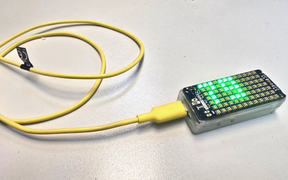
Well, I had to develop my own device. As always, we take the S7V30 module as a basis.
All bibliography on the S7V30 project is collected here
Open project of a Wi-Fi logger via USB, CAN, RS-485, RS-232 — here is the first publication on the predecessor module of ours
Open project of an embedded module for IoT — the scheme and design of the first version of the module. In the current version, only the SPI Flash chip has been added
Development of a universal PLC for home appliances — here is about where our module is used
How to make fast Wi-Fi for PLC — here is about how we accelerated Wi-Fi in our module
Architecture, planning, and implementation of DMA in Synergy microcontrollers — here we dive into the technology of fast data transfer within microcontrollers.
Making a bootloader with cryptographic protection for Synergy based on Azure RTOS — here is the first version of our universal and secure bootloader described.
Setting a password on an SD card using a web application on jQuery, Azure RTOS web server, and Synergy — and here we found a non-trivial application for our module. With its help, you can lock SD cards. Almost a hacker tool.
Open project of a Wi-Fi Bluetooth micro-router. Deploying all the necessary stacks on the module to truly integrate it into IoT.
Experiments with an accelerometer and gyroscope on the S7V30 platform. How to easily make an orientation sensor in space.
The S7V30 module is equipped with an autonomous power system, non-volatile real-time clock, high-speed Bluetooth and Wi-Fi modules (with UDP bandwidth of over 100 Mbps), USB charging and internet access via USB, as well as a 6D IMU chip with low power consumption. The device operates on the open Azure RTOS framework with support for exFAT, NetX Duo, GUIX, and other drivers. This makes the module a serious tool for recording real-time activities with an IMU sampling rate of up to 1666 Hz and creating data files of tens of gigabytes in size.
How the tracker is controlled
While running, there is no time to search for and press buttons on such a small device. Therefore, control is carried out using gestures. Gestures include turns in a given orientation, single and double taps, shakes, and other actions. In the settings available through the web browser, you can specify which gestures and with what intensity turn the device on, off, and switch its modes.
This control became possible thanks to the presence of the ISM330DLCTR chip on the board. I talked about this in one of my articles. At that time, I did not touch on the low-power modes of this chip, but its interesting feature is the ability to detect mechanical impacts with ultra-low power consumption. The chip can determine changes in orientation, single and double clicks, vibrations, tilts, as well as free-fall state, consuming only 10 microamps.
As it turned out, in sleep mode, the chip poorly distinguishes strong mechanical impacts from each other. For example, it can easily confuse a single tap with a double tap or a change in orientation. However, what the chip really excels at is reliably detecting the moment of free fall. For example, you can set the device to turn on and off when thrown to a certain height. This makes accidental turning on or off of the device almost impossible.
Choosing an LED Matrix
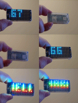
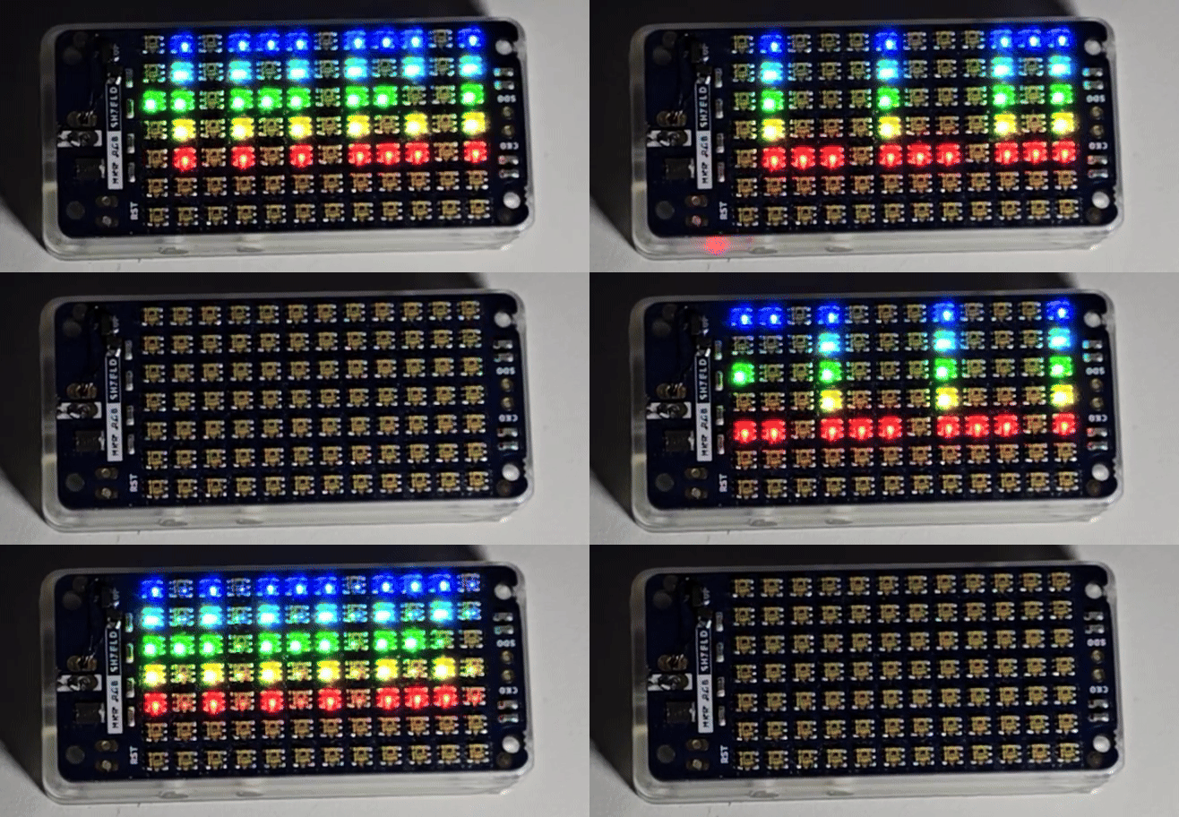
We choose the MKR RGB Shield as the display. I have already used this module in the previous project. The APA102 LEDs of this shield are interesting because they work through the SPI interface, which allows the use of the microcontroller's DMA mechanism, unlike the WS2812 LED matrices. The SPI interface speed for APA102 exceeds 3 megabits per second, which also matters.
Tuning the MKR RGB Shield to Reduce Power Consumption
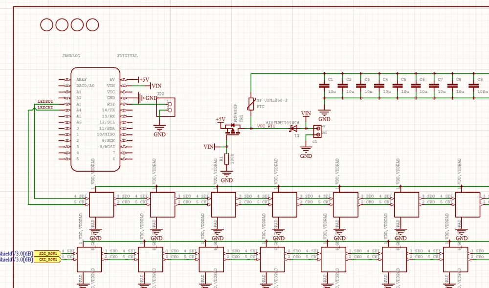
The problem with the MKR RGB Shield for autonomous devices is the high power consumption even when the LEDs are off. Therefore, it is necessary to perform a small tuning of its circuit. Here is what the original MKR RGB Shield circuit looks like:
When all the LEDs are off, the MKR RGB Shield consumes 30 mA from a 3.7 V battery.
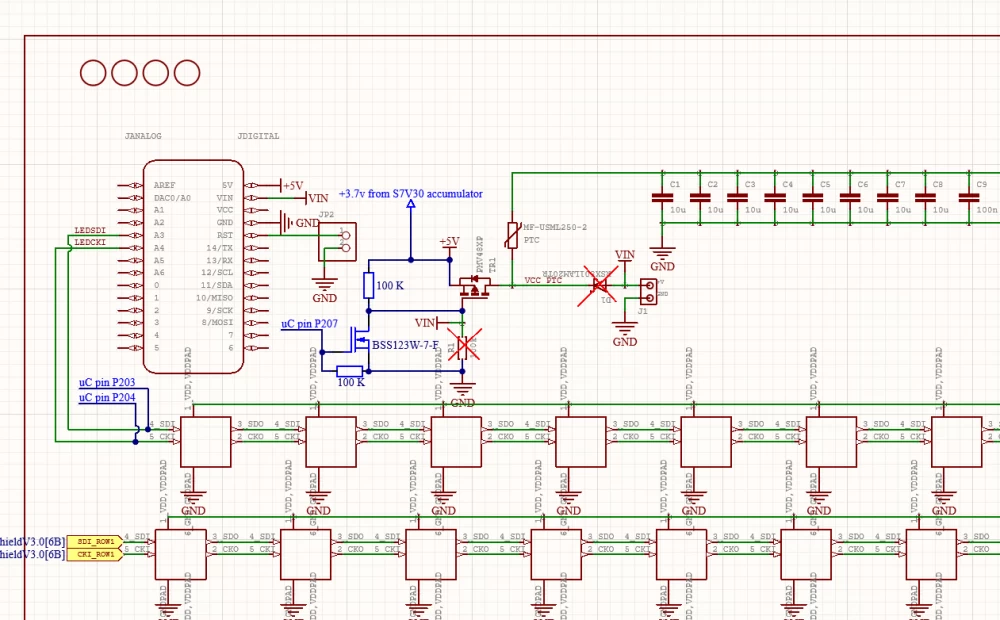
After tuning, the circuit looks like this:
An additional transistor controlled by the microcontroller serves to completely disconnect the shield from the battery. As a result, its power consumption is reduced to less than 1 µA (leakage, however).
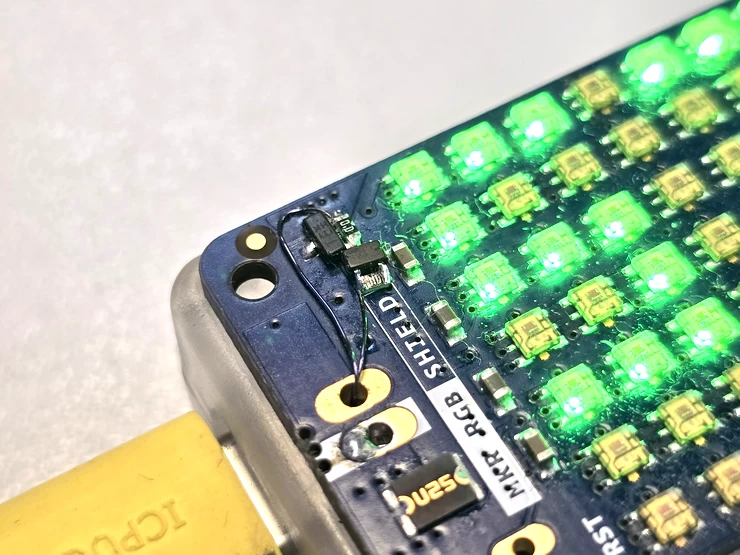
The tuning on the board looks like this:
Working on the Trainer
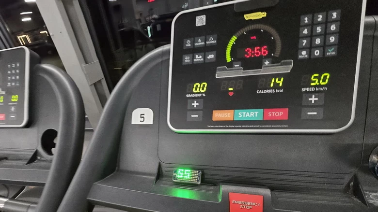
Trainers like the one in the photo are capable of receiving ANT+ packets. Since chest heart rate monitors often transmit heart rate data in ANT+, you can immediately see your heart rate when you get on the trainer. Or someone else's, as the trainer does not authenticate heart rate monitors via ANT+. Our device with a heart rate monitor performs pairing via Bluetooth LE, so it always shows data only from the specific indicated heart rate monitor.
Which Heart Rate Monitors are Compatible with Our Device and How to Connect Them
Our device is compatible with all Bluetooth heart rate monitors that have a service with UUID = 0x180D in their Bluetooth profile.
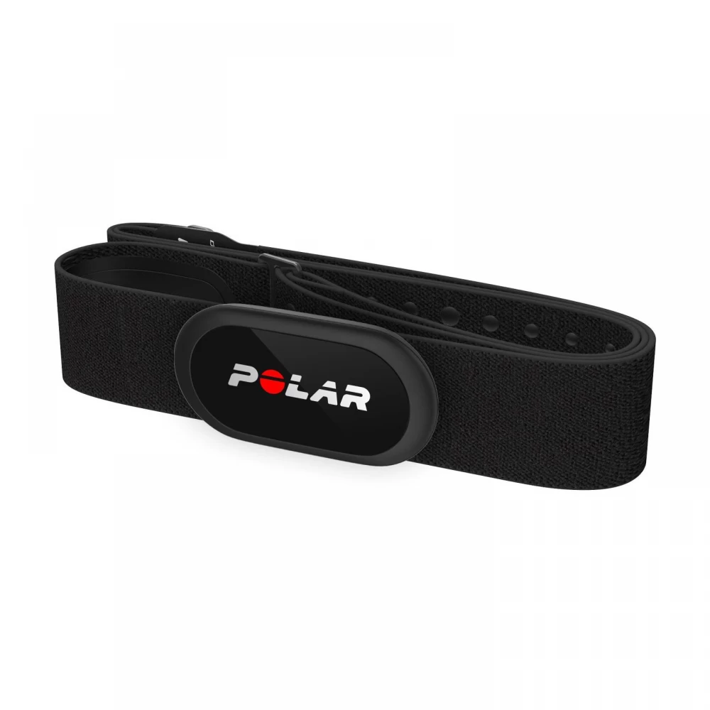
Testing was done with POLAR and GARMIN heart rate monitors.
The heart rate monitor is connected through the terminal. To do this, you need to press the sequence: 4 - 1 - O.
When a device with UUID equal to 0x180D is detected and matches our model, press H. A list of detected heart rate monitors will be displayed, each of which will be connected and its data read, including the serial number.
Select the desired one and press Enter. The device details will be saved in memory. After that, you need to reset, and the pulse display will be ready to work.
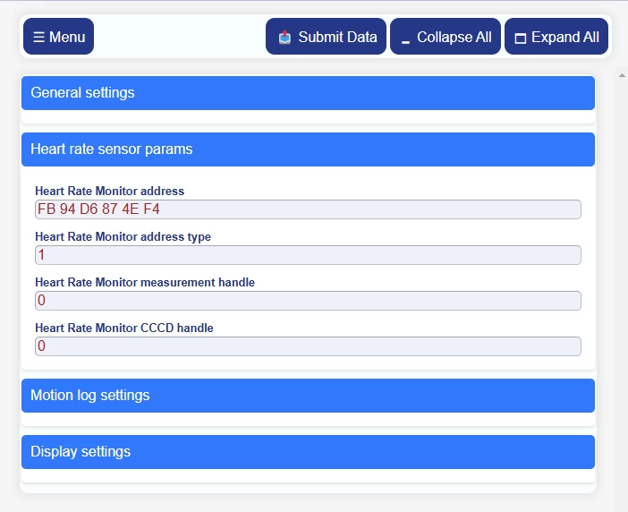
You can immediately record the heart rate monitor details in the device settings via the terminal or through the WEB interface:
The sensor address, Handle, and CCCD Handle can be found using programs like nRF Connect.
In addition, the device allows you to simply display arbitrary text.
Software
The project repository is located here.
The project is compiled in the IAR Embedded Workbench for ARM 9.60.3 environment and written in C.
The project contains 3900 files, most of which are files of the universal software framework of the S7V30 platform, which includes, in particular:
The real-time operating systemThreadX.
Middleware Eclipse ThreadX: FileX, NetX, GUIX, USBx.
Software packageSynergy, including basic drivers for Azure RTOS.
PackageWi-Fi Host Driver (WHD) from Infineon.
PackageBTSTACK Library from Infineon.
Thanks to this framework on the S7V30 platform, you can quickly create a wide range of applications in the field of IoT and automation. And yes, here again, a whole windowed GUI engine GUIX is used to output several numbers. This makes it possible to replace the LED matrix with a TFT display with large fonts and widgets in just a couple of minutes.
The framework is isolated and does not depend on the main application. It can be compiled separately and used to create other applications.
The source code of the final application is located in the directory src. The directory may contain artifacts from other planned applications. Do not let this confuse you.
The file Motion_sensor.c contains a task that directly works with the IMU chip. By default, this task immediately starts recording gyroscope and accelerometer data in real time to a file. This file can then be downloaded from the device's FTP server and analyzed in MATLAB. For convenience, there is a corresponding script for importing data in the MATLAB directory. In addition, the task can still have a direct communication channel with MATLAB in real time via Wi-Fi or USB, as demonstrated in this project.
The entire tracker application takes up 6% of the processor time in operation. If working through the WEB interface or downloading files, the load increases. The maximum current when Wi-Fi is running at full speed is 200 mA. This does not include the current consumed by the LED matrix. The matrix consumes an average of 50 mA in pulse indication mode.
Full consumption in Deep Software Standby mode
We toss the device and it goes into so-called "active sleep"
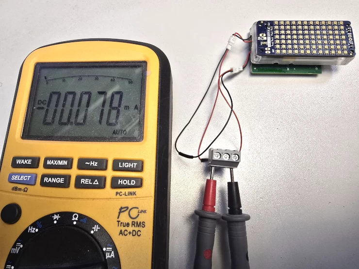
In general, the entire device with the active ISM330DLCTR, the microcontroller in Deep Software Standby mode with the contents of the Standby SRAM preserved, active clock and battery charge counter (the module diagram is given here), consumes 78 µA at room temperature.
The device has a built-in 500 mAh battery. And with such a battery, the device will last at least 200 days in active sleep.
Conclusion
Frankly speaking, the tracker is not particularly economical. In the future, it will be necessary to think about a more energy-efficient solution. However, this is just a demonstration and research project, and much cannot be demanded from it. Its functions and usability are still being studied.






Write comment