
- DIY
- A
How to assemble a remote-controlled car
Surely everyone played with remote-controlled cars in childhood. In 2024, I had the idea to assemble my own car. As they say, "The first 40 years of a boy's life are the hardest."
The project is based on 2 Arduino boards, as well as a Chinese kit that includes 4 motors (just like the Audi Quattro) and a "base" on which all the components are placed. A complete list of all modules will be provided below.
The project creation process can be divided into the following stages:
Creating a circuit
Purchasing components
Assembly/soldering
Programming
First, you need to understand: what will the car actually be?
Nothing complicated, the car is a platform with 4 wheels. The wheels are stationary, and turning is done by changing the speed of the right and left wheels or by completely stopping them. For sharp turns, the wheels rotate in opposite directions. This is called a tank turn.
The circuit is powered by 2 18650 batteries and a charging module. The batteries with a nominal voltage of 3.7 V are connected in series, i.e., the final voltage is about 7.4 V. When they are fully charged, it will be slightly higher.
Commands from the remote control will be transmitted via radio channel, so you need 2 radio modules for the remote control and the car.
All this will be controlled using 2 Arduino Uno, as the simplest and most affordable way. For such projects, it is better to use the Nano version, but at that time I already had 2 Uno, and I didn't want to wait.
Creating a circuit
We start by thinking through the "power" installation. There is no need to invent anything, there are plenty of circuits on the internet. However, most of them describe the connection of 2 motors, and we have 4 on board. After some searching, I managed to find a circuit for 4 motors.
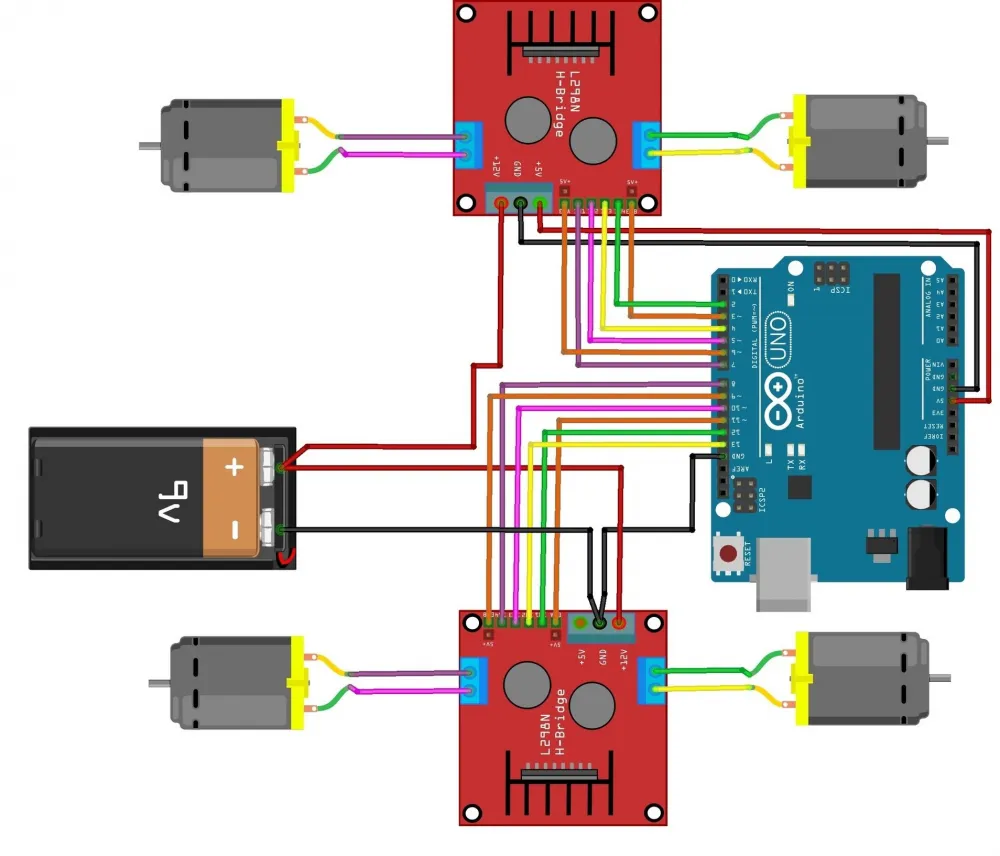
The main connection diagram is found, so it just needs to be slightly modified.
The circuit uses a Krona as the power element, but since this project uses batteries, the Krona needs to be replaced with a power module.
It remains to add the radio module and it's ready... But here's an unpleasant moment. The module works according to the SPI protocol, and the SPI lines, according to the diagram above, are already occupied. We will have to slightly modify the circuit. The radio is connected to the SPI outputs of the board, and the motor driver control is switched to free pins. You need to be careful, as it is necessary for the board to support analog mode on the connected pins.
The final circuit turned out to be like this:
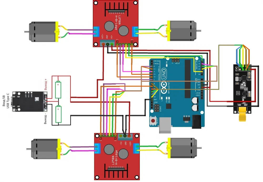
Note that for space saving, the diagram shows 2 buses. From the radio module - brown with a green stripe and from the second driver - gray with an orange stripe. The wire colors are taken from the initial diagram, but the final project was assembled with more convenient colors, so they will differ in the diagram and in the photo, but this does not make the diagram inoperative.
As we can see from the diagram, Arduino will not be able to take on the power load of the motors, so control is carried out through 2 drivers.
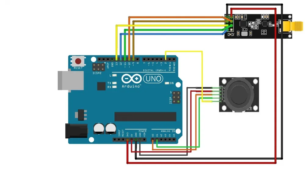
For the control panel, the circuit looks much simpler. We choose the radio module connection scheme and add a joystick to it. The power supply of the remote control is carried out via the standard USB Type-B connector on the board.
Component procurement
The final set required for assembling the toy:
Arduino Uno - 2 pcs.
Joystick
Radio module nrf24l01 - 2 pcs.
Motor driver L298N - 2 pcs.
Car assembly kit (4 motors, 4 wheels, platform)
Battery 18 650 - 2 pcs.
Li-ion battery charging module Type-C 2S USB BMS 15W 8.4V 1.5A with balancing
Battery compartment
Assembly
The assembly itself is not complicated if you follow the diagram. But it will still not be possible to assemble quickly, as there are quite a lot of wires, it is difficult to track them. There will not be much soldering, in this project only the wires to the motors and to the charging module are soldered. The rest is connected to the Arduino pins.
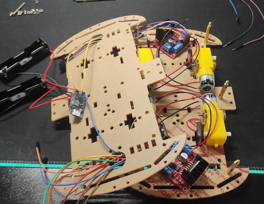
At the lower level, the engines and their drivers are fixed. The remaining modules are located on the upper platform. For reliability, large elements can be secured with clamps.
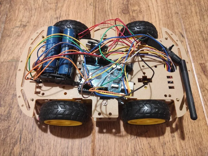
It turned out to be such a Frankenstein. In the future, it is planned to carry out cable management and print the outer case for the machine on a 3D printer. For now, as they say: "It does not affect the speed".
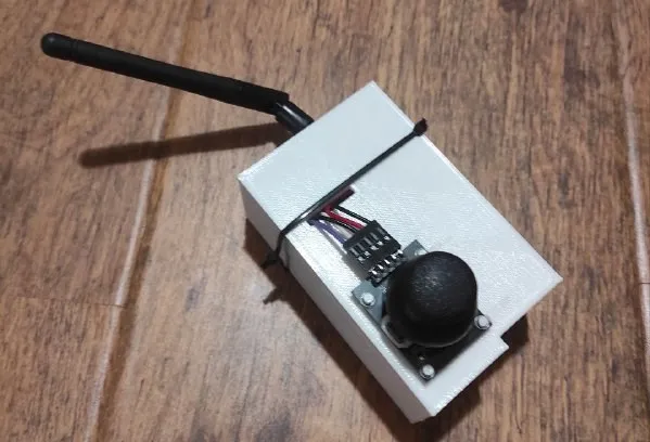
Assembling the remote control is not difficult, so I will attach only the finished version with the case here. The case is printed on a 3D printer, but that's another story....
The hardware part of the circuit is assembled, which means you can put the batteries on charge and start developing the software.
Programming
Software development is carried out in Arduino IDE 2.
Below will be links to full sketches (as Arduino programs are called), and here I will give only a description of the main loops and some functions.
If you are a beginner, you need to upload the Car.ino sketch to the car controller, and CarControl.ino to the remote control controller.
Nothing complicated happens in the main code of the remote control. Readings are taken and sent via the radio channel. Make sure that the unique radio channel IDs on the remote control and the car match in setup().
void loop() {
  indications[0] = -(analogRead(pinX) - 512);
  indications[1] = -(analogRead(pinY) - 512);
  radio.write(&indications, 4);

  delay(100);
}
All the logic is embedded in the controller on the car. The main loop code is given below.
void loop() {
  if(radio.available()){ // If data has been received in the receiver buffer
    radio.read(&indications, 4); // Read the potentiometer readings
    power = indications[0];
    turnPower = indications[1];

    int motorPower = map(abs(power), 0, 512, 0, 255);
    int motorTurnPower = map(abs(turnPower), 0, 512, 0, 255);

    if (power > 10) {
      forward();
      setSpeed(motorPower, turnPower);
    } else if (power < -10) {
      back();
      setSpeed(motorPower, turnPower);
    } else {
      if (turnPower > 10) {
        right();
        setSpeed(motorTurnPower, 0);
      } else if (turnPower < -10) {
        left();
        setSpeed(motorTurnPower, 0);
      } else {
        disable();
        setSpeed(0, 0);
      }
    }
  }

  delay(50);
}
If the settings in setup() of both boards match, the data will be automatically received and sent to a temporary buffer. Then we read this buffer and if there is something there, we place the received data into local variables.
Thus, we get 2 variables. The value along the Y and X axes, which corresponds to the 'power' forward/backward and the 'power' of the turn. To control the signal strength, the arduino accepts a number from 0 to 255, and the numbers received from the stick are in the range from -512 to 512. The received signals are converted to the range [0; 255].
Now we have 4 variables:
The value along the X axis in the range [-512; 512]
The value along the Y axis in the range [-512; 512]
The absolute value along the X axis in the range [0; 255]
The absolute value along the Y axis in the range [0; 255]
The values themselves are used to determine the direction, and the absolute values are used to send control signals. In all conditions, checks for the minimum value of 10 are used, since the stick by default sends a non-zero value. The stick is at zero, but the arduino thinks it is slightly deflected. Such a feature.
Next, we follow the following logic: if the stick is strongly deflected forward, we set the forward motion. If backward, then reverse. If the stick is stationary along the Y axis, we check the X axis and if the joystick is deflected along it, we activate the in-place turn mode in the desired direction. If none of the above conditions are met, we turn off the motors.
A little about the functions. Enabling forward/reverse or in-place turn mode is done by applying low and high signals to the driver. Signal values for different modes can be found in the description of the L298N driver.
Below is the function for calculating the power for each motor.
void setSpeed(int power, int turn) {
  if (turn > 30) {
    analogWrite(PIN_ENA, power);
    analogWrite(PIN_ENB, map(power - turn, 0, 512, 130, 255));
    analogWrite(PIN_ENA_2, map(power - turn, 0, 512, 130, 255));
    analogWrite(PIN_ENB_2, power);
  } else if (turn < -30) {
    analogWrite(PIN_ENA, map(power - turn, 0, 512, 130, 255));
    analogWrite(PIN_ENB, power);
    analogWrite(PIN_ENA_2, power);
    analogWrite(PIN_ENB_2, map(power - turn, 0, 512, 130, 255));

  } else {
    analogWrite(PIN_ENA, power);
    analogWrite(PIN_ENB, power);
    analogWrite(PIN_ENA_2, power);
    analogWrite(PIN_ENB_2, power);
  }
}
If the turn power values are less than 30 in either direction, the turn value is ignored and the pure Y-axis value is sent to the control pins, i.e., we move forward or backward.
If there is a turn value, i.e., the stick is deflected along both axes simultaneously. For example: the upper right corner. Then you need to move forward and turn the car to the right.
This mode of operation is implemented by supplying a reduced power value to one of the sides. If we want to turn right, the right wheels rotate slower than the left ones. This is achieved by subtracting Y - X and recalculating the range [0;512] to [130;255]. The initial value of 130 is set so that the wheels do not lock completely when turning (although this sometimes happens).
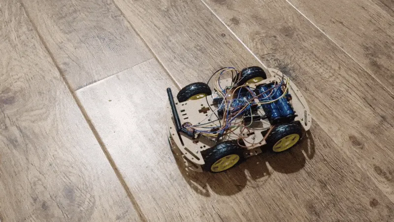
It remains to upload the programs to the controllers and it's ready. You can play!
Full versions of the sketches:


Write comment