- DIY
- A
How to significantly increase the range of WiFi / BT reception using a soldering iron
Or more precisely, using two soldering irons. An unexpectedly simple and effective solution suitable for compact modules with a chip antenna, requiring no additional costs.
Or more precisely with the help of two soldering irons.
Introduction
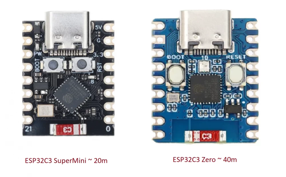
You have a WiFi / BT module with a soldered chip antenna, like the ones shown in the picture below. They have a confident reception range within 10m, which does not satisfy you at all. Attempts to programmatically increase the transmission power help to increase the range to 20m, but you want much more.
Solution
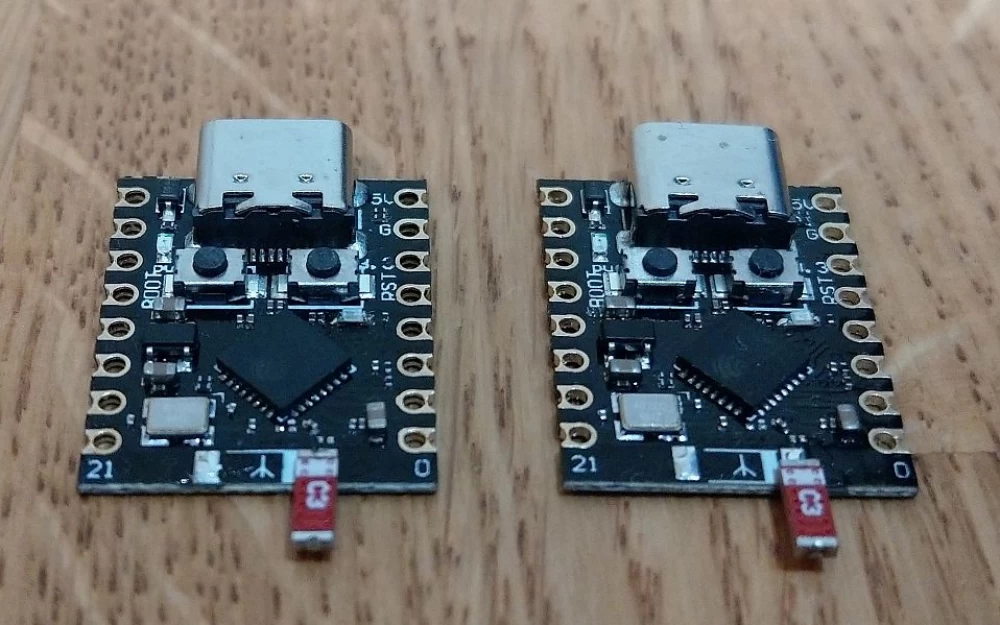
With the help of two soldering irons, we desolder the chip antenna and solder it by one end, turning it perpendicular to the edge of the board, as shown in the picture under the article title. For this pair of modules, the range (with increased transmitter power) increased from 20m to 100m.
Why it works
The short answer is because the range was sacrificed for the compactness and cheapness of the board.
The chip antenna is a reduced version of the monopole antenna. In this case, it is simply a printed circuit board on which a spiral antenna is formed. It should work no worse than a whip antenna, provided it is properly mounted. The main problem is with the mounting. It is more or less obvious that the antenna should be positioned perpendicular to the ground plane. However, I have not seen a single compact board where this condition is met. After all, with the correct orientation of the antenna, the dimensions of the board will increase by a few millimeters along with its price, which is completely unacceptable.
So, manufacturers of compact modules always place the antenna parallel to the edge of the board and the ground plane. But even with such incorrect placement, there are nuances. The figure above shows two modules with the same ESP32C3 processor and the same antennas. However, in experiments, they showed a communication range that differed by a factor of two. The fact is that on the board on the right, which showed twice the range, the antenna is separated from the ground plane by a 2mm gap, while on the board on the left the gap is less than a millimeter. The smaller this gap, the more the electromagnetic field is concentrated in the gap between the antenna and the ground plane instead of radiating into the surrounding space. The antenna behaves more like a capacitor, its matching with the transmitter is disrupted. The power taken from the transmitter drops, and most of it turns into heat by currents induced in the ground plane.
A simple rotation of the antenna to the correct position solves all these problems, radically increasing the range of confident reception. Moreover, experiments with an external antenna soldered instead of a chip antenna did not reveal any difference in the range of operation between the external antenna and the chip antenna in the correct position.
Experiments with antennas were carried out as part of the universal BT adapter project




Write comment