- DIY
- A
Used Antminer S9 for the radio amateur
There have already been several articles on tekkix about using old Antminer S9 control boards, which are currently sold at an affordable price. I decided to create something useful for the radio amateur. Today I will tell you about the project of another antenna switch. In the 21st century, it will have an FPGA and a dual-core ARM processor.
In one of my previous articles, I talked about the antenna switch project for satellite antennas. Time passed, and 4 antennas seemed insufficient, so I decided to install more, resulting in 7 antennas. However, running new control cables to the roof turned out to be a complicated task: coordinating with the homeowners' association killed the idea right away. I decided to switch antennas using the wiring I already had. In the end, I concluded that I could allocate only 3 wires for control. Two were immediately used for power and ground, leaving one wire for signal transmission.
I went through all the available protocols that work over a single wire, and eventually decided to use DTMF signal transmission. They are low-frequency, interference-resistant, and transmit well over regular PVC cables.
DTMF (Dual-Tone Multi-Frequency) is a two-tone multi-frequency analog signal. It is used in telecommunications and voice systems to send commands or signals over a voice channel via a telephone or similar communication device. DTMF is based on a tone matrix where each row corresponds to a high-frequency group and each column corresponds to a low-frequency group. Pressing a key on the telephone keypad generates a combination of one signal from each group. For example, pressing the "1" key generates a tone composed of the low-frequency tone "697 Hz" and the high-frequency tone "1209 Hz".
Fortunately for me, our Chinese friends manufacture several convenient modules that allow controlling relays using DTMF.
Here is what I used in the project:

The AE11A04 encoding and transmission module has the ability to operate either through a parallel interface to the microcontroller or by simply pressing buttons. The latter feature proved invaluable for testing the program.

The programmable relay module DTMF Relay MT8870. It receives DTMF commands and switches relays. I use it in a mode where only one relay is activated at a time, i.e., when a command is received, all relays are turned off, and only one relay corresponding to the received DTMF code is turned on. The module has 8 relays, but I use only 6. Importantly, the module does not respond if it receives a DTMF code greater than 8. I use this feature to send confirmation signals for relay activation.

If someone thought that these relays are used for switching antennas, they are not. They only activate the windings of this high-frequency 6-port coaxial relay.
I wanted to make sure I could verify that the switching command was accepted and the necessary relay was activated. So, I needed some confirmation signal to indicate that the relay was on. I organized it as follows: upon receiving the command, one of the 6 relays is activated. For this, tone signals from 1 to 6 are used. Then, a circuit involving several 555 timers and diode-transistor logic comes into play. When any relay is activated, the circuit forms a set of signals for the transmission module in such a way that, in response to the relay activation, a DTMF signal is transmitted with a code that is 8 more than the number of the activated relay. That is, when receiving a DTMF signal 1, relay 1 is activated, and the signal with DTMF code 9 is sent back. All this happens on a single signal line, so the relay board also receives this command but does not react to it in any way. The signal is received by the control panel through another module:

This module only has an interface with the microcontroller, and it serves to receive the confirmation signal.
To ensure that the signals reach the relays and back, I also installed low-frequency amplifiers on the line using PAM8403 modules:

This is a digital low-frequency amplifier, which is ideally supposed to be loaded onto a speaker, not the communication line. Therefore, to match all signal inputs and outputs with the single transmission line, I used transformers from an old telephone apparatus. Such a transformer has three windings. One is used as the load for the amplifier instead of the speaker, the second is connected to the DTMF receiver, and the third winding is connected to the transmission line.
During debugging, it was found that the activated amplifier interferes with the reception of signals even if it is not transmitting anything. The PAM8403 has a shutdown signal, which can be controlled by the microcontroller. I use this feature to turn on the amplifier only when transmitting the DTMF signal. In this case, it almost does not interfere with reception. Almost, because if an external signal of sufficiently high level is applied to the output of the switched-off amplifier, something inside the amplifier starts to limit the signal. Maybe it's diodes in the MOSFETs, maybe something else. It doesn't matter. Adding various filters and signal limiting circuits solved the problem completely. I managed to organize two-way DTMF transmission over a single wire, which was the original goal. The only thing left is to connect all of this to the Antminer S9.
As I mentioned earlier, all DTMF modules have a parallel control interface. 4 data bits and a strobe signal for transmission. I thought that I didn't want to deal with a large number of signal lines, so I immediately made adapters to the modules from the I2C bus using the widely known PCF8574 chips.
As I worked on the project, I wanted to add a lot of different things:
Information is displayed on a color display. For this, I took a 2.4-inch SPI display with an ST7789 controller.
A keyboard to control the relays. I used a cheap matrix telephone keyboard. I didn’t bother with programming and bought a TCA8418 controller module for the keyboard.
For sound control of key presses on the keyboard, I added a piezo speaker.
I use a dipole antenna for antennas and decided to add control for turning the dipole on and off to the design.
For controlling DTMF code transmission, I added a separate low-frequency amplifier and a small speaker. In the old days, the connection speed was determined by the sound of modem beeps, and now I can determine which antenna is on just by listening to the DTMF exchange, without looking at the display.
A current consumption meter on the INA226 module. This is an invaluable diagnostic tool for understanding how everything works on the roof in the switchboard. Many faults can be diagnosed by current consumption.
USB-UART adapter based on FT232. Used for connecting to a computer and controlling antenna power on/off from the computer.
Thus, for my project, the following is required:
I2C bus for DTMF transmitters and receivers, current sensor, and keyboard.
SPI bus for the display.
Separate relay control lines for the dipole antennas.
UART for communication with the computer.
I write all this in detail because the Antminer S9 is a board based on the Zynq7010 FPGA, and all these interfaces need to be configured for operation in the Vivado/Vitis CAD. I use Vivado 2022.2.
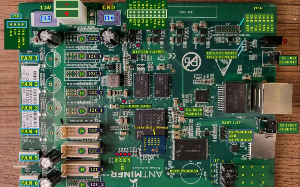
Most of the signal lines on the board are routed to connectors as shown in the picture:

Some contacts can be redefined, but buses, such as I2C, are definitely routed. Looking at this picture, you need to figure out which contact will carry which signal. This correspondence is then configured in the constraints of the Vivado project.
The next step is to create a new project in Vivado for the Zynq7010. There is already enough information on both Tekix and the internet on how to create a project for the Antminer S9 board. It makes sense to take a basic project where the main settings are already made. On the Astralab website (https://astra.org.ru/) and its associated Telegram channel, there is a lot of information on this topic. If you start everything from scratch, you will need to configure clock generators, DDR, NAND memory access, and basic peripherals like the Ethernet port.
Next, you need to configure the buses we need. Most settings are done in the ARM Zynq core settings form. There, the SPI, I2C buses are enabled, and GPIO ports are defined.
For my project, I used the FPGA capabilities only to a small extent. But for the first time working with FPGA, I think it’s sufficient. I used UART lite to organize a serial port, also added a counter controlled from GPIO. It generates a frequency of about 1 kHz, which I use to drive a “buzzer”.
The complete project diagram in Vivado looks like this:

It’s important to note that simply enabling the I2C bus in the processor block is not enough. The illustration shows that you also need to add buffers to provide bidirectional data transfer on the bus.
The only block written in Verilog is the counter for the "buzzer" operation. Its code is very simple:
module khz_gen
#(
    parameter   CNT_MAX = 16'd49_999   // Parameter definition parameters (macro definition)
)
(
    input   wire    sys_clk,
    input   wire    sys_rst_n,

    output  reg    buzzer_out
);

reg     [15:0]  cnt; // 16 -bit width counter

/* Counter CNT */
always@ (posedge sys_clk or negedge sys_rst_n)
    if(sys_rst_n == 1'b0)  // When the reset signal is valid (when reset), CNT clear zero
        cnt <= 16'd0;
    else if (cnt == CNT_MAX)   // Count the maximum value, CNT clearing zero
        cnt <= 16'd0;
    else
        cnt <= cnt + 16'd1;    // Self -increase every clock rising along CNT 1

/* Buzzer device controlled by counter */
always@ (posedge sys_clk or negedge sys_rst_n)
    if(sys_rst_n == 1'b0)   // Initial state
        buzzer_out = 1'b0;
    else if (cnt == CNT_MAX)  // CNT is remembered once, the output level reverses once
        buzzer_out = ~buzzer_out;
    else     // CNT is not full, buzzer level is maintained
        buzzer_out = buzzer_out;

endmodule
After setting up the buses, they need to be mapped, as I mentioned above, to specific pins and signal lines on the Antminer S9 board. This is all described in the constraints file roughly as follows:

One of the difficult moments for me was determining the GPIO port numbers. The thing is that Zynq has, simply put, two GPIO buses: one (MIO) is connected to the processor core, and the other (EMIO) to the FPGA. The signal numbering in each bus starts from 0. However, for example, when specifying the GPIO number in the devicetree, continuous numbering is used. MIO pins from 0 to 53 retain their numbers, while EMIO numbers start not from 0, but from 54. But that's not all. When a GPIO pin is mapped in Linux, its number changes again. In my case, the GPIO number in Linux is 11 less.
Now we run the bitstream generation. After successfully completing the generation, we export the Hardware with the bitstream included. The resulting XSA file is used to create the FSBL bootloader.
Open Vitis, create a new FSBL project for Linux, specify the previously exported XSA file from Vivado as the source. Start the project build. As a result, the FSBL bootloader file fsbl.elf should be created for the designed system.
These were all the mandatory steps for using the Antminer S9 in your project. After this, there are many options. You can write an application program for the device directly in Vitis using C++, or first build Linux for the device and then write the application program for the Linux OS. It's up to each person to decide which is more convenient, but I think that using Linux is optimal, though it is quite a complicated path. A full guide is described on the Xilinx website https://xilinx-wiki.atlassian.net/wiki/spaces/A/pages/460653138/Xilinx+Open+Source+Linux
There are many options for running Linux as well: you can use different kernels, builds, file systems, etc. All of this confuses beginners.
For myself, I decided that I need a simple Linux that will boot from the SD card, and the root file system will be completely in RAM. There is no need to write anything to disks for the antenna switcher to work, and internet access is also not required. So, I need a rather basic Linux version that could run my control program and that's it.
As a digression, I’ll mention that before building the OS, you traditionally need to create the OS bootloader. The U-Boot system is usually used for this purpose. In the Xilinx git repository, there are ready-made sources configured to build U-Boot for the Antminer S9.
git clone https://github.com/Xilinx/u-boot-xlnx.git
cd u-boot-xlnx
git checkout xilinx-v2022.2
So it’s worth just taking them and compiling.
cd u-boot-xlnx
export CROSS_COMPILE=arm-linux-gnueabihf-
export ARCH=arm
make distclean
make bitmain_Antminer_s9_defconfig
make
In my configuration of U-Boot, I removed the watchdog support, otherwise, I left everything as is. If you plan to use the Antminer S9 board in multiple projects, you can use the once compiled U-Boot in each project. Unlike FSBL, which may change with changes in the Vivado schematic and needs to be recompiled with each change in Vivado, U-Boot does not require such attention.
The Antminer S9 board has a system UART port. Most likely, you will need a USB-3.3V to UART adapter to connect to the port. This port can be used to access the U-Boot console, configure it, and write the Linux boot configuration file. The command to boot Linux from the SD card in U-Boot is approximately as follows:
fatload mmc 0 0x4000000 image.itb; bootm 0x4000000;It is also useful to configure the IP address there for TFTP-based OS loading. Loading a new OS kernel over Ethernet during debugging is much faster than writing to an SD card.
The Antminer S9 board also has a JTAG port, but the connector is not soldered. I didn't need JTAG for the project, but it could be useful for complex debugging.
A good guide on how to build the appropriate Linux version I found here https://github.com/farbius/linux-vitis-zynq. I did almost everything as described there. It uses the option to configure an external tree for building buildroot. You just add the specific files you need to the appropriate folders, and in the project configuration file, you specify which packages to include in the build. Then you run the compilation and get the finished Linux image with the ready root filesystem.
My Linux build script is as follows:
mkdir -p tmp/
cd tmp/
fold="buildroot"
if [ -d "$PWD/$fold" ]; then
  echo "Buildroot repo is already cloned"
else
  git clone https://github.com/buildroot/buildroot.git
  cd buildroot/
  git checkout tags/2023.05
  cd ..
fi
mkdir -p zynq_lin
cd zynq_lin/
make --directory=../buildroot/ BR2_EXTERNAL=../../external-tree/ zynq_defconfig O=$PWD
make
In my simple case, in the external-tree, I first modified the devicetree (the system-top.dts file), where I enabled the I2C, SPI, UARTLite, and Ethernet buses, and specified GPIO pins. Fake devices on the SPI and I2C buses are listed in the file. This is necessary for proper initialization.
Next, I configured the Ethernet interface, setting static IP addresses. Although Ethernet is not needed for the system's operation, it's convenient for file loading and updates. You don't have to remove the SD card every time for an update, you can simply connect to Linux via SSH and upload the new files.
The build is based on the prepared Xilinx Artix-7 Linux, which is already configured for Zynq7000, and I only included support for UARTLite, SPI, and removed all Python packages.
The final touch is to auto-start my application program using an init script. I store the application on the SD card outside the root filesystem. This allows me not to recompile the whole image when changing the application program.
We run make and go for tea, as the kernel and filesystem build takes quite a while. In the end, we get the finished Linux image. The final step is to build the boot image for the SD card. For this, we will need all the previously compiled files: the Bitstream from Vivado, FSBL.elf, u-boot.elf.
Preliminary, you need to prepare a boot.bif file with the following contents:
img : {[bootloader] fsbl.elf system_top.bit u-boot.elf}This command creates the bootloader:
bootgen -image ./boot.bif -o i ./BOOT.bin -log debug From all of this, we get BOOT.bin, which we write together with Linux (the image.itb file) to the SD card. (Don’t forget to set the jumpers on the Antminer S9 board for booting from the SD card).
I’m describing all the previous steps very superficially and schematically because they have been repeatedly covered on both tekkix and in numerous online guides for Zynq7000. The important thing is to go through this process at least once, after which building Linux for Antminer S9 won’t pose any problems.
After all these lengthy manipulations, we finally get a system on which we can run the desired application program. The only thing left is to write it.
Here I must make one more note. In my project, I decided not to use interrupt handlers to avoid writing loadable kernel modules for Linux. That is, for example, I read key presses from the keyboard by regular polling. The hardware certainly supports interrupt handling, but I didn’t want to study Linux driver writing. So, everything is kept simple. But the project isn’t complicated, as the CPU load measurements show it doesn’t exceed 3% in this mode. It’s important to understand that the computational capabilities of Zynq far exceed the resource needs of the application. Almost any Arduino would have worked, but for a low price, we have the Antminer S9, so why not take advantage of using it for a hobby project?
As a Rust enthusiast, I didn’t miss the opportunity to write the control program in this language. I had previously written for STM32, where it was either a single thread or asynchronous stuff in embassy, and here it's a whole new world – full Linux with threads, hundreds of megabytes of RAM, and other perks. One can afford almost everything and still not fully load the system. However, I didn’t use the graphical subsystem of Linux; working with the display was done using the embedded-graphics crate.
For development, I used almost the same crates as for embedded programming for STM32. Since the interfaces for rust embedded hal are practically the same for STM32 and Linux, the code is very similar. The main difference is, of course, in initialization and access to physical devices like SPI, I2C, delay, etc. The driver code remained almost the same.
For example, to access the pins in Linux, I use the crate gpiocdev-embedded-hal. Access to the pin is done like this:
let pin_dc = gpiocdev_embedded_hal::OutputPin::new("/dev/gpiochip0", 55, PinState::Low)
                .unwrap_or_else(|_err| {
                    println!("Couldn't open pin55.");
                    process::exit(1);
                });
pin_dc.set_high().ok();
For accessing I2C, the standard linux-embedded-hal is used:
let i2cdev = I2cdev::new("/dev/i2c-0").unwrap_or_else(|_err| {
            println!("Couldn't open i2c");
            process::exit(1);
        });
let i2c_cell = AtomicCell::new(i2cdev);
let i2c = AtomicDevice::new(&i2c_cell);
As described in my previous implementation of the antenna switch (https://habr.com/ru/articles/820145/), the new version also supports the easycom protocol for communication with the PC, but in an even simpler version, sufficient for synchronization with the PST-Rotator program.
The Antminer S9 board is quite large, so the entire construction is assembled in an old Mini ITX case. The display and keyboard covers are printed on a 3D printer. Here’s how it turned out:

The screen displays information about the coordinates of the satellite that the antennas are pointing to, the number and aperture of the connected antenna, the relay activation status, etc.
Finally, a photo of the antennas installed on the roof, for which all this was set up to switch. The metal cabinet contains the relay block.

All the original texts of the described program and Linux assembly can be found on GitHub at the link (https://github.com/lesha108/antswitcher.git)
In the next article, I will explain how I use the Antminer S9 board for the project of a specialized sequencer for the transceiver. I believe that due to its low cost and rich functionality, this board will serve as the basis for many more amateur radio projects.


![From Virtual Hands to AI for Survivalists: Curious Open Agent OSes [and One Hardware Project]](https://cdn.tekkix.com/imgs/2026/05/habrcom/big/ce0b1057616faed51cd8b9f3b2b9.webp)

Write comment