- DIY
- A
DIY CO2 Laser CNC Machine Electronics
When I was assembling my first CNC laser, all the guides on DIY machine electronics were on YouTube. Only videos. In real assembly, it's a torture. Find the right moment. Remember. Pause. Rewind. Pause again. And so on.
Years have passed — almost nothing has changed. So I did it differently. No videos, no rewinds. Text and detailed diagrams. Extremely clear. Not a universal “one correct” option. A working example that can be repeated or adapted to your own mechanics and components.
In this article, I explain how I assemble the electronics for my machines. I am self-taught and some things here may well be non-optimal or even erroneous.
If you notice such moments – I would appreciate your advice in the comments.
Trocen AWC7813 Controller
The heart of the electronics for our laser machine will be the Trocen AWC7813.
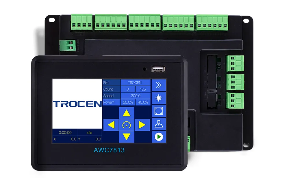
It has built-in support for working with two motors on the Y-axis. It can align the Y-axis using two limit switches by itself. Therefore, we won’t need a separate portal alignment board.
Here’s what the electrical diagram of the laser machine looks like from the official documentation:
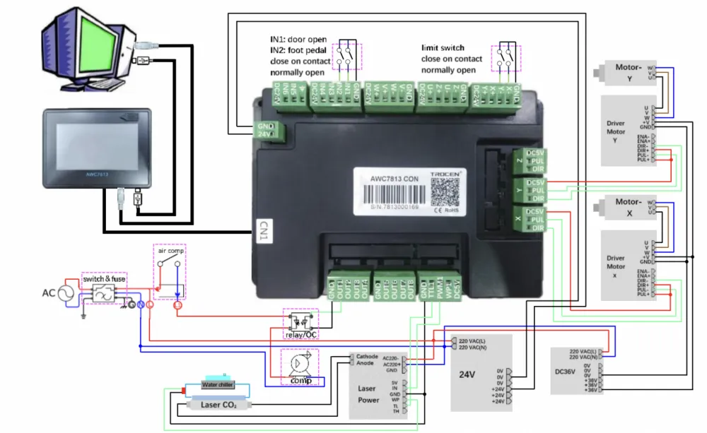
In principle, the article could end here. If it weren’t for wanting to make just a couple of changes:
The cable connection between the control panel and the portal is at the connectors. Because it's very convenient to be able to disconnect the panel from the machine. When the machine needs to be transported somewhere. Yes, you might not have to transport it. And all this will be in vain. But if you do have to, you will definitely understand that it was the right choice.
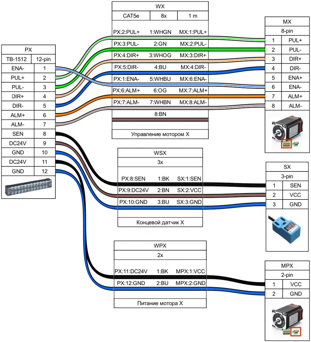
The switching on the portal is done at the terminal blocks. Because it's convenient and clear. To replace a burnt-out end sensor, there’s no need to reassemble the entire cable harness from the portal to the control panel.
There are two Y motors. They operate synchronously. They are aligned by two end sensors.
The control panel of the machine has a block layout. The main panel only has the controller and power supply. Everything else is connected externally. If a blow pressure control unit is needed, we connect it. If it's not needed, we live peacefully without it.
There is one power supply. But it's powerful. At 24 volts, 350W. Mean Well LRS-350-24.
And yes, there are no motor drivers in the control panel. Because we will use hybrid NEMA23 motors with built-in drivers. Just like these.
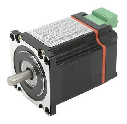
The beauty of hybrid motors is that when they encounter an obstacle, they stop and go into error. They don’t try to damage the mechanics of your brand-new machine. Or you. By throwing the accelerated portal off the rails towards you.
Built-in drivers save space. Yes, this is a less repairable design. In case of a driver failure, you will have to replace the entire motor. And buying these motors in Russia is not that easy. In terms of availability. These nuances need to be understood before applying them in your machine.
Controller Connectors
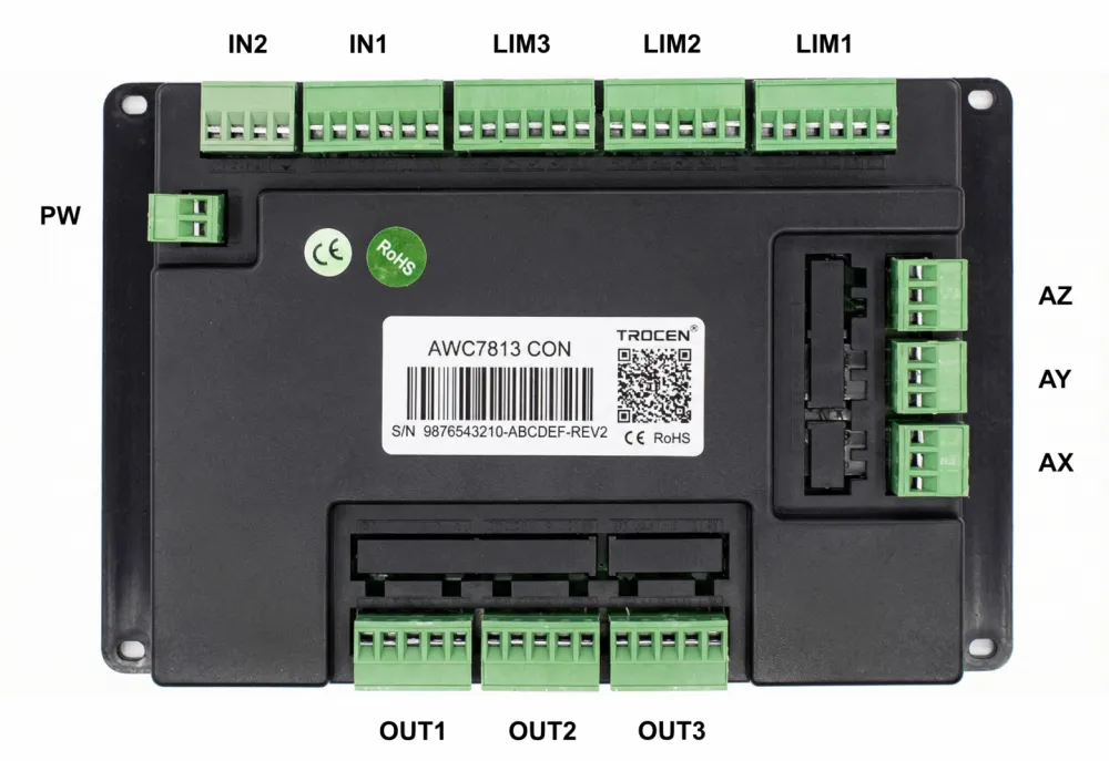
For some reason, the manufacturer did not think to label the connectors. Neither on the controller itself. Nor in the documentation. Well. We will do it for him. Because we will need the names of the connectors in the wiring diagrams.
Electrical Panel
First, we will connect the connectors of the machine axes. We have three axes. Each axis has a motor and an end inductive sensor hanging on it.
A feedback signal ALM comes from the motor to the controller. It is activated in case of a motor error. All three signals from three axes are fed into one input of the controller. An error in any of the motors should stop the program. I haven't tested this myself yet. Once I do, I will remove this comment.
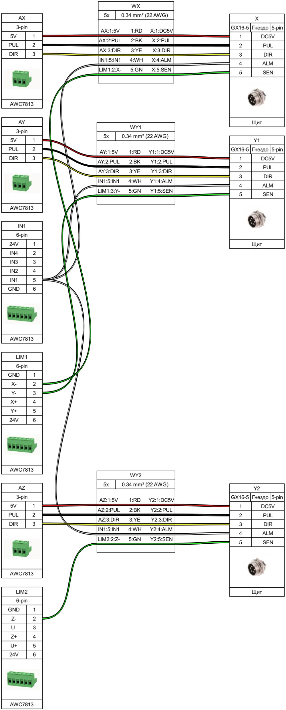
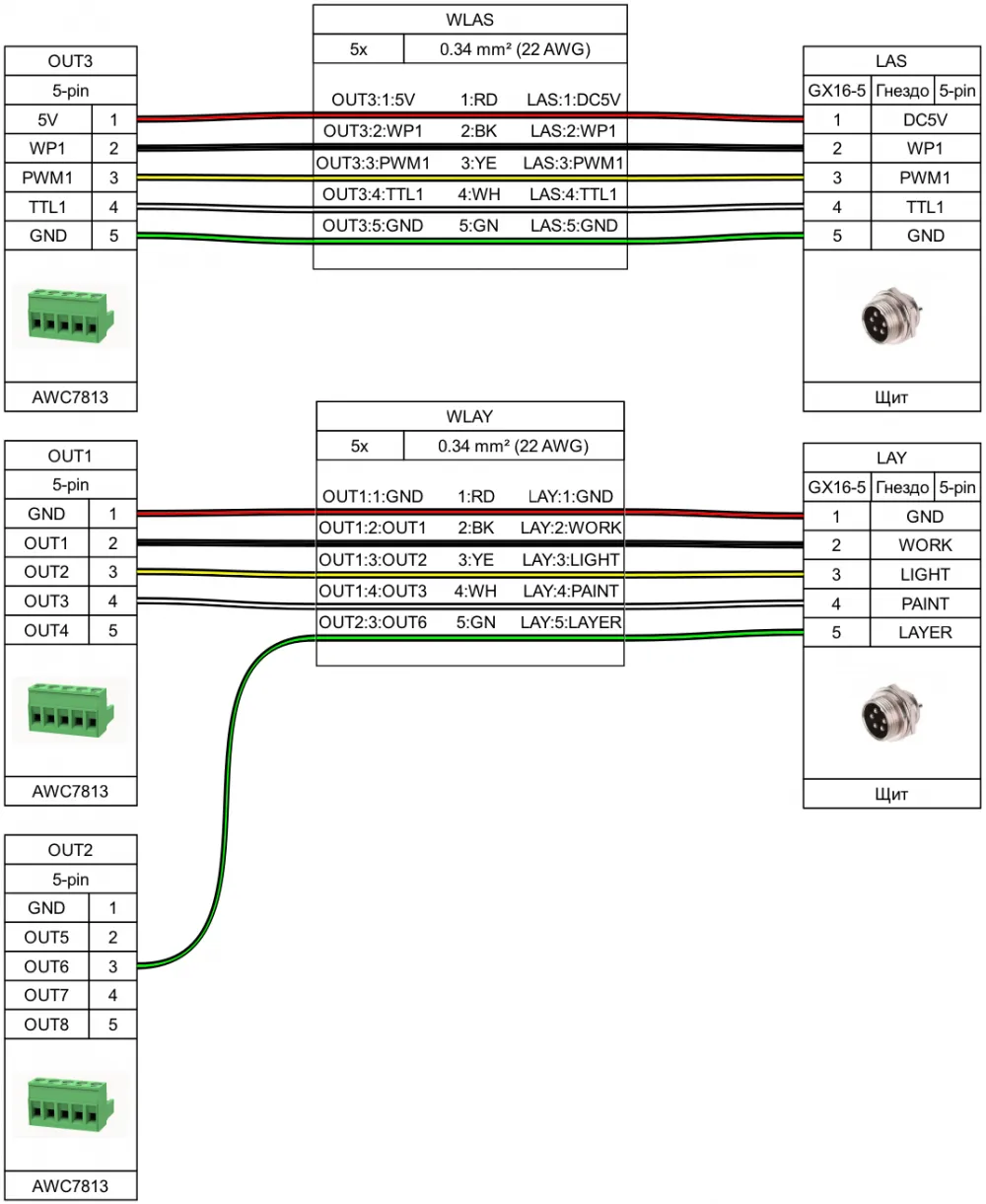
Next are the control outputs for the high-voltage power supply of the laser (LAS) and the automatic pneumatic control output (LAY). The controller can automatically turn on air cooling only when performing a task. And switch between two levels of airflow – for engraving and for cutting.
If you are using a normal adult compressor instead of an aquarium one, the automatic cooling feature will be very useful. We will discuss it in a separate article later.
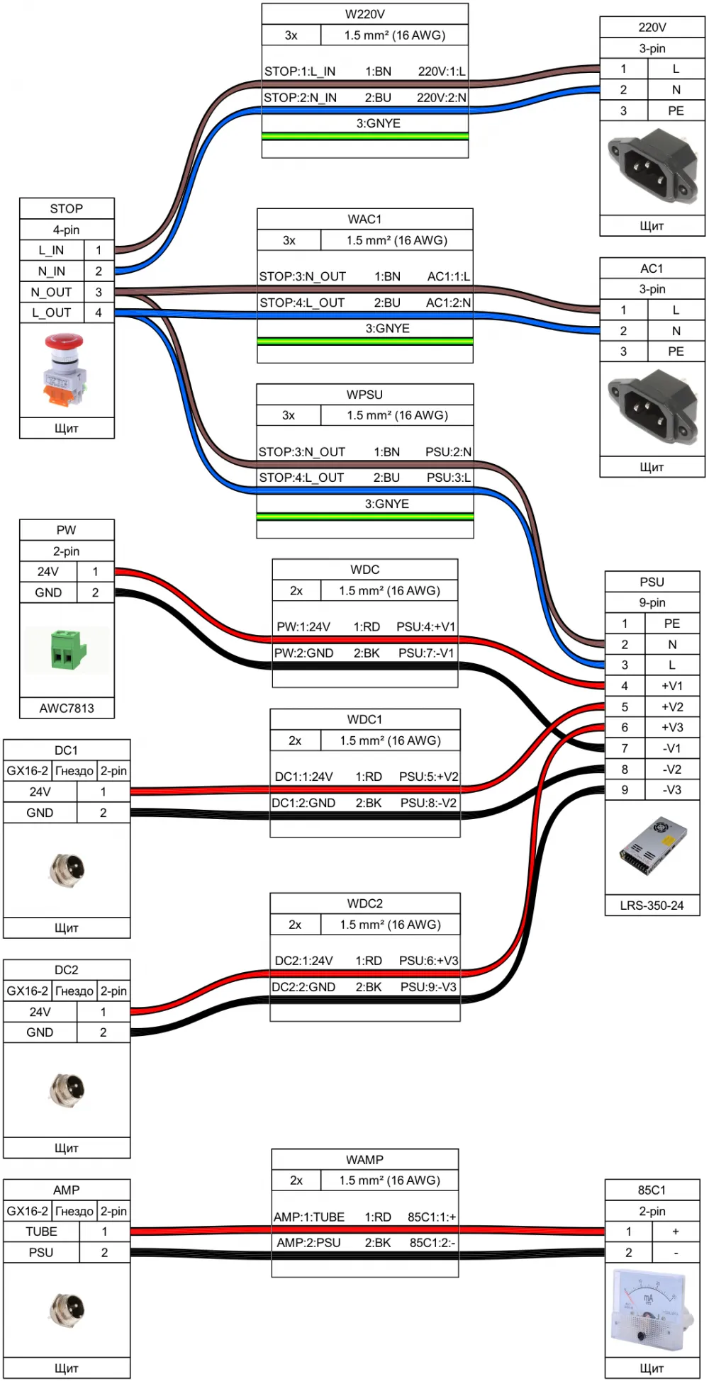
And here is the final part of the shield diagram. Power through the STOP button. And a microammeter.
There are two DC outputs on the shield – DC1 and DC2. The first one goes to the portal to power the motors and limit switches. The second one is a backup. For example, for an external automatic cooling unit.
The microammeter shows the actual current passing through the laser tube. Trendy control panels for ignition units sometimes lie. It is extremely desirable to have a reliable analog measuring device in the system. One that does not lie. It is placed in the break of the negative wire of the laser tube.
In the diagram, I couldn't figure out how to properly draw the connection AC1/PE -> PSU/PE. A limitation of the tool used. The ground must be connected to the power supply. And to all AC* output connectors.
The AC1 output is used to connect the high-voltage power supply for the laser tube. More on that below.
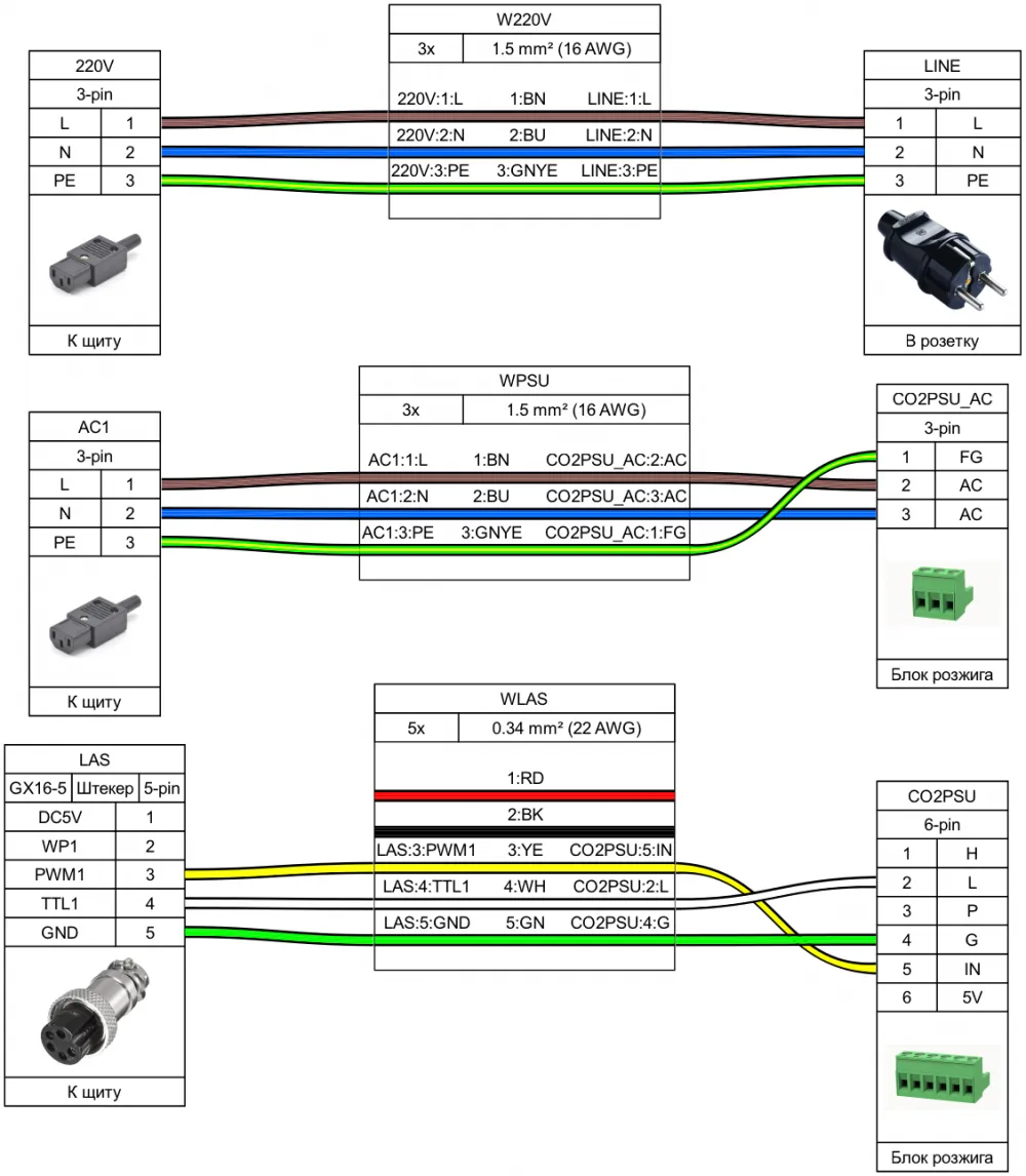
And the very final part of the shield diagram. Connection of the external high-voltage power supply for the laser tube. The ignition unit. And connecting the shield itself to 220V.
Cable Route
Three cables go from the shield to the portal – X, Y1, Y2, PWR. The axes are connected at the portal on terminal blocks of the TB-1512 format. Each axis has its own block.
The diagram does not show that the power is transferred from one connector to another. This is noted in the comments on connectors PY1/PY2.
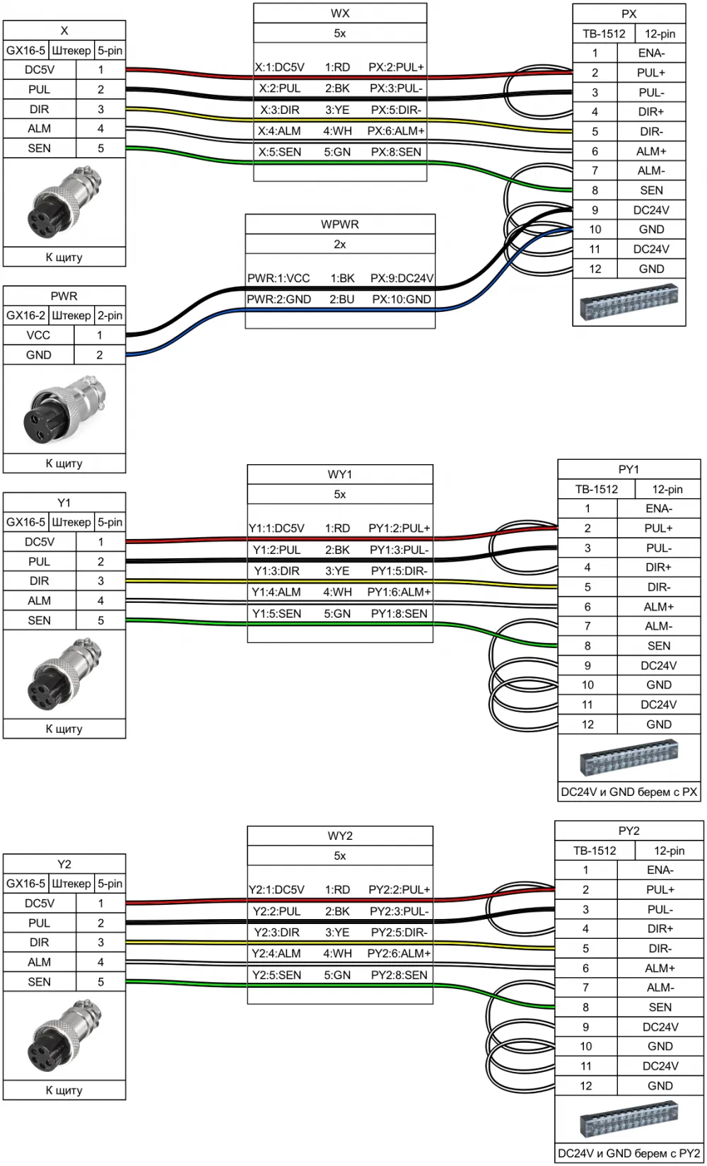
Portal
The axes are connected in the same way. Each axis to its own connector. The diagram shows one axis. A twisted pair was used for connecting the motor control connector.
Epilogue
The connection diagrams were created using the wonderful tool https://github.com/wireviz/WireViz. I highly recommend this product to anyone who wants to organize their documentation on cable connections.
This article is part of the documentation for the 5CNC Laser.Master kit. With it, you can build a CO2 laser CNC machine with a large working area by yourself. It is not very easy and not without some tinkering, but it can be done).

Write comment