- DIY
- A
Swing Sets for Adults - Oscillating Circuit
It seems that most of us swung on "swings" as children :-), while some, even in adulthood, do not cease this activity — and we will not be talking about base jumping and similar trendy things, but rather a much more interesting activity — the application of "swings" in electronics: the use of oscillatory circuits…
The mention of "swings" above is not accidental, as even the name "oscillatory circuit" suggests to us that we are dealing with a certain "oscillatory," or if you like, "wave" process.
Oscillatory circuits are quite widespread in electronics, and therefore, if you have not yet encountered them, it makes sense to slightly unveil this question, as mastering such a fundamental building block of electronics provides new opportunities that you will be able to apply flexibly. So…
The phenomenon of the oscillatory circuit was discovered quite a long time ago (approximately, it's the second half of the 19th century — the peak of electrical research and discoveries), and a number of researchers agree that it was not a discovery in itself, but rather the result of numerous studies by a whole series of scientists (W. Thomson, B.V. Feddersen, H. Hertz, etc.), who successively formulated the laws of oscillatory processes, which ultimately culminated in a specific device and its concept.
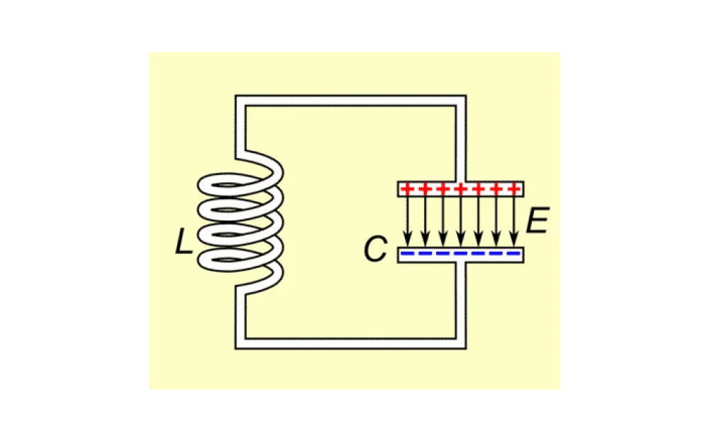
In electronics, an oscillatory circuit is called a system consisting, at a minimum, of a power source, a capacitor, and an inductive coil — connected by conductors either in series or in parallel, into a single circuit (the series connection is shown below; the explanation of the parallel connection will come a bit later):

The system works as follows: suppose the capacitor was charged by some current, after which the circuit was closed and a current starts to flow through the circuit, which, passing through the coil, creates an electromagnetic field in it and around it, and at some point, when the capacitor is fully discharged, the current through the coil stops, and this field cannot disappear instantly — therefore, it is said that the field begins to collapse, generating a current in the opposite direction — which again starts to flow in the circuit, recharging the capacitor with current of reverse polarity.
Such oscillations can occur multiple times until all the energy initially stored in the capacitor is completely spent (in the absence of external replenishment).
That is, we see that the oscillatory circuit represents in every sense a certain realization of those very "seesaws," where energy is constantly transferred: from that stored in the capacitor — to that stored in the magnetic field* and vice versa:
*The energy storage in the magnetic field also includes the rotation of magnetic domains (magnetic moments of the atoms of the substance) if a ferromagnetic core is used.
The concept of its quality factor is inseparably linked with the oscillatory circuit, where the meaning of this concept, if said simply, lies in how long the oscillations in the circuit do not dampen and, for the most part, the magnitude of the quality factor depends on the self-capacitance of the inductive coil and the resistance of the circuit (the resistance of all conductors).
In this circuit, the inductive coil represents a winding of conductive material, wound either in the form of a cylinder or in the form of a spiral — where the spiral implies the winding of the conductor in one plane, in a single layer*.
*Here it should be noted that we are talking about the simplest option, where the inductor has one layer, while at the same time, it can contain a whole series of layers—and it all depends on the task: generally speaking, it can be said that the number of layers allows to increase the "inductance" of the coil—that is, how much energy the coil can store in the magnetic field (in simple terms).
An inductor can either have a ferrite core or be wound without one: generally speaking, it can be said that there are 4 options for choosing a specific solution:
there is little space structurally, so we increase inductance by placing a core;
we do not want to wind many turns, we need to achieve a high inductance and we have a suitable ferrite core at hand—therefore we use the option with a core;
there is no suitable ferrite core, so we are forced to wind relatively many turns, in relatively many layers, to achieve the necessary inductance;
the system will operate at relatively high frequencies (about 100 MHz and above), therefore, we are forced to abandon the core and use only wire winding, since at such frequencies the core will not work effectively and will heat up—the reason for this will be the inability of magnetic domains (what this is will be discussed below) in ferromagnetics to quickly align with changes in the magnetic field, and therefore, the ferrite will stop working as a magnetic field storage, and all the energy of the magnetic field will go into heating it.
Moreover, the inductor can be (as mentioned above) wound in a plane, in the form of a spiral, or in the form of cylindrical winding.
In general, in addition to relying on the 4 options listed above, the choice of a specific design solution can also depend on:
purely production moments (a flat coil can be made, for example, in the form of an etched spiral track on a printed circuit board, where, thus, compactness of the device and simplicity of production are achieved, as well as high repeatability of parameters);
as well as the necessity to work at high frequencies, where the flat coil, all else being equal, has a lower inter-turn capacitance (by 30-50%, on average), compared to the cylindrical one.
What inter-turn capacitance means: we know that two parallel conductors connected to power represent a capacitor, right? And here this effect is fully observed, where due to the parallel arrangement of the turns of the conductor, a capacitance arises between them — that is, a capacitor is formed.
This leads to the fact that, at a certain frequency, a sort of parallel current path is formed, which leads to the self-resonance of the coil and, all else being equal, the smaller the capacitance of the coil, the later this will occur — that is, this will determine the maximum allowable frequency of the coil.
It should be noted right away that here and thereafter, we will first consider the concept of the resonance of the coil itself, and then the resonance of the system (oscillatory circuit), where the former is rather a negative phenomenon if the coil operates as part of the circuit, while the latter is the normal operating mode of the oscillatory circuit.
So, the resonance of the coil:
It may seem that there is nothing wrong with resonance, since often, in different systems, we, on the contrary, try to achieve this infamous resonance!
However, in this case, resonance is a negative phenomenon, because simply put, the system ceases to function as we intended — that’s all — that is, the minus is not in the resonance itself, but in the fact that our design collapses: the coil begins to introduce an unforeseen element into the oscillatory circuit (if we did not take this into account).
As we know, the capacitance of a capacitor depends on the proximity of the plates to each other, where, all else being equal, the closer the plates are (as far as the physical properties of the material allow, without breakdown), the greater its capacitance.
Based on this, one way to combat the parasitic capacitance of a coil is simply to space the turns apart from each other — for example, in the case of cylindrical winding, this can be done if the winding is performed with two wires at once: after which, one of the wires is unwound back. Thus, it turns out that a neat gap is formed between the turns, the width of one wire*, which we unwound.
*Not necessarily the width of one wire, it can also be more.
Interestingly, this operating mode of the coil (in resonance) is also specially induced, as in this case, you can save and eliminate the capacitor: for example, this can be used to create a barrier to a certain signal at a specific frequency, where the occurrence of resonance in the coil prevents it from passing (a classic example is the choke coils on the cathode of a microwave oven, which block the output of microwave radiation outside the oven).
Or, for example, a similar approach is used in so-called "extension coils" of antennas, which allow virtually extending short antennas of receivers/transmitters, which, for example, otherwise would have to be 10m long but will instead be half a meter long (the numbers are conditional, so please do not get too attached to them).
The downside of such an approach is only that it is not flexible, meaning you need to wind the coil very precisely to achieve resonance at a specific frequency, whereas using an external capacitor would make it easier — you would just need to change its capacitance, for example.
But the resonance of the coil is just an element that needs to be accounted for so it does not interfere with plans, while the resonance of the oscillatory circuit is its standard operating mode — therefore, when designing the coil and the oscillatory circuit as a whole, it is done in such a way that the potential resonance frequency of the coil is several times higher (2-3) than the working frequency of the resonance of the oscillatory circuit.
The operation of an oscillating circuit in resonance is necessary to, put simply, obtain the maximum benefit from minimal impact: in this mode, it will consume minimal energy from the source to maintain oscillations, which in itself implies high selectivity, that is, focus on a single frequency.
And this, in turn, implies that:
for example, if we have a transmitter, its energy will not be wasted and will be concentrated only on one frequency for the most efficient transmission of information, where the actual transmission will require minimal energy;
in the opposite case, if we have a receiver — this will imply that we will be able to receive even a weak signal, as it will be maximally amplified.
An oscillating circuit can be created either by a series or parallel scheme, which can be read in detail at the link.
By the way, if you go to the link and look at the diagrams, it is easy to notice that at the very beginning of the article a series diagram is provided. ;-)
What this is needed for: in the first case (series circuit), the voltage can be increased, while in the second case (parallel circuit), the current can be increased.
Thus, in the first case, for example, weak radio signals can be amplified by raising the voltage level of the signal received by the antenna or, for example, collecting high-voltage devices (the same electric shock!), and in the second case, provide the consumer with a powerful current from a relatively miniature and weak power source (microwaves, welding machines, etc.)
Also interesting, we saw, from the principle of operation above when considering how the oscillating circuit works, that the very ideology of the oscillating circuit implies a wave process, where the positive half-wave is replaced by the negative half-wave and a bipolar capacitor is used in the design — and the scheme itself implies power from an alternating current source.
However, it is curious that another option is also possible — powered by a direct current source (for example, a battery or accumulator)!
For this, one or more transistors are added to the circuit, which must turn on at specific moments, pump power, and then turn off — thus, providing pulse power, where, if one transistor is used, the power is supplied only in one half-cycle, or, for example, if two transistors are used, they can operate alternately, supplying power in each half-cycle.
In this case, if we take, for example, the blocking generator circuit (a voltage boosting generator), one can notice an interesting point that it works without resonance, solely due to the impulse pumping of the coil by the transistor :-) — that is, we see here that the topic is somewhat broader than it may seem at first glance… ;-)
With the above knowledge on the oscillatory circuit, one can try to assemble one of the simplest receivers/transmitters on the Colpitts generator.
For calculations, one can try using a calculator — here, with which, for a specific frequency, and the capacitor available, you can calculate the inductance.
After that, for this inductance, using another calculator calculate the physical dimensions of the coil for the available wire: number of turns, diameter, winding length, and required wire length.
Finally, it can be said that interesting experiments with the oscillatory circuit do not end only with the development of your own version, as the oscillatory circuit can be used as an element of your radio transmitter on a microcontroller (esp32/arduino, etc.) — in other words, creating your own custom radio transmission channel without using the standard transmitter!
Where, for example, a microcontroller generates a signal that is sent to the GPIO pin, which is picked up by an oscillatory circuit and transmitted at a certain frequency, while another microcontroller, as an option, can receive and decode this signal! :-)
This results in a completely custom radio transmitter... In the process, it will also be necessary to study coding during transmission, noise filtering, etc. — in general, this activity can turn out to be quite interesting and developmental...;-)


Write comment