- DIY
- A
Catching time in DCF77 format
In the comments to the exact time server, it was suggested to add DCF77 as another time source in addition to NTP and GPS. And I finally made it, although as a separate device, and since the technology here is analog, there were its own nuances.
As a reference:
DCF77 is a radio station broadcasting precise time from atomic clocks; that is its main purpose.
It is located in Europe, in Germany, near Frankfurt. It broadcasts on long waves across all of Europe, covering parts of the ex-USSR as well. It transmits a signal containing time and date information, UTC+1/UTC+2 depending on "daylight saving time".
It also transmits local weather and can be used as an alert system, but that's of little concern to us.
The operating frequency is 77.5 kHz – hence the name "DCF77".
Its signal can be used for self-setting electronic clocks, for which inexpensive modules are produced that can be embedded in various devices, there in Europe.
But here, all of this works quite poorly.
The problem is simple: distance.
Despite the high power of the transmitter and the good propagation of long waves over long distances – 2000 km is still 2000 km.
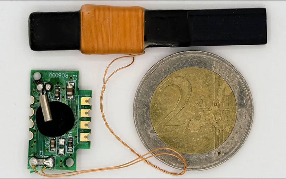
A typical DCF77 module has a compact magnetic antenna, which is probably convenient to place in standard table clocks:
Generally, for receiving electromagnetic waves, there are two types of antennas: electric and magnetic, corresponding to the electric or magnetic component of the field.
Electric ones – a piece of wire, a metal rod, a pattern on a PCB – their dimensions must correspond to the wavelength (1/4, 1/2, 1); wavelength depends on frequency and the speed of light (approximately in meters = 300000000 / Hz), so for high-frequency signals like cellular or WiFi they are very convenient.
But for frequencies like 77500 Hz, the wavelength is 3.870 km (hence they are called long waves), and a more or less working antenna should be about a kilometer long (1/4 of 3.870).
For such frequencies, it's more convenient to use magnetic antennas: essentially a coil of wire wound on a rod (and sometimes without one).
There are nuances regarding the fact that the coil should be correctly oriented relative to the magnetic field lines of the wave - but that's a detail.
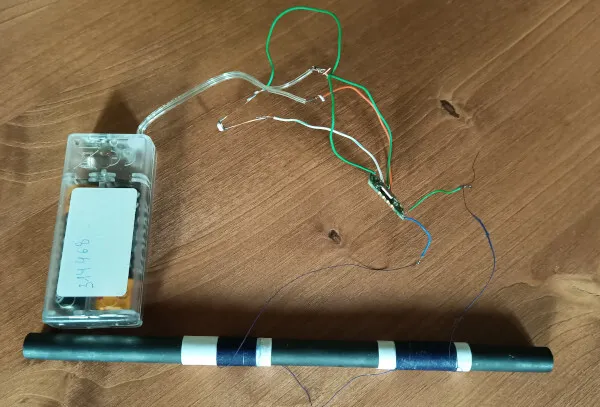
Here's an example, as in the case of this module: a ferrite rod with windings.
But you can't fool physics: size matters, the larger the rod, the more pronounced the effect.
A small magnetic antenna probably works well in Europe or nearby.
In my case, it turned out to be insufficient for stable signal reception: either noise or nothing at all.
Here, it's worth saying what we're actually catching?
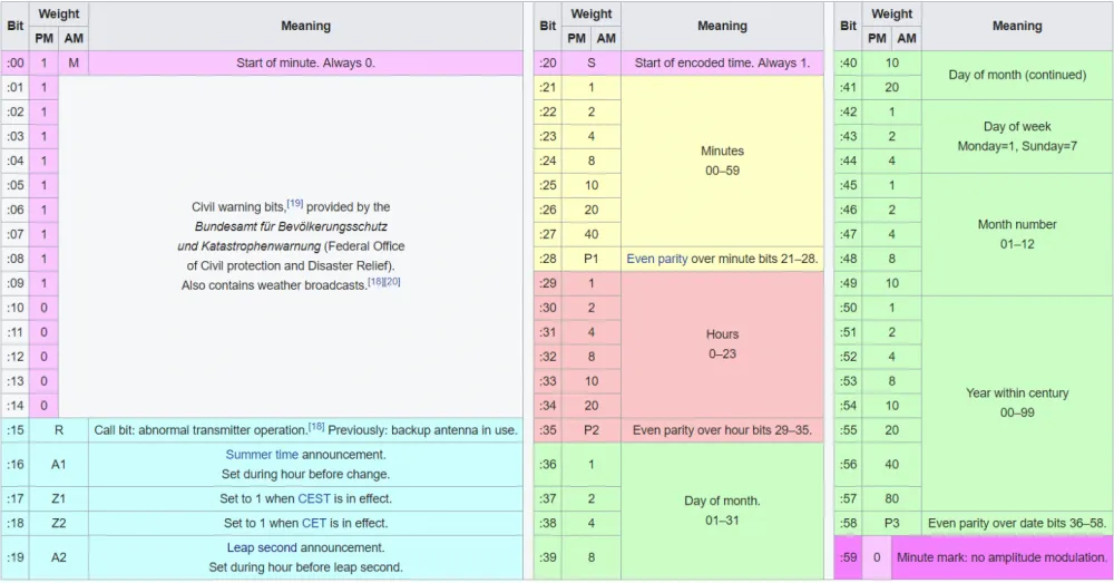
DCF77 simply transmits a certain signal, which is interrupted once a second for a specific duration. A 0.1-second pause means a logical "0", a 0.2-second pause means a logical "1". No pause means the end of the cycle. Then transmission starts again.
The length of one cycle is 60 seconds, the length of the message is 58 (or 59, depending on how you count) bits.
Decoding table (from Wikipedia):
The RC8000 module, which is supposed to catch this, receives the signal, only inverts it, so instead of pauses, there are pulses: ideally, they should be 0.1 seconds or 0.2 seconds.
It doesn't decode the signal into code; it simply receives and filters the analog signal.
And when it can't receive a quality signal, it either "remains silent" or starts spitting out random pulses at random times because it's catching interference.
Here's another important digression: the propagation of radio waves over long distances is significantly influenced by the state of the planet's ionosphere, which can change substantially under the influence of radiation from the nearest star.
In short, long-distance communication is better at night, and what can't be caught during the day might be caught at night. If you're lucky, that is.
In this case, even night didn't help; the module either remained silent or spat out garbage.
The remaining option was to try to increase the size of the magnetic antenna.
To do this, you need to take a larger ferrite rod, wind a coil around it, and connect it instead of the standard antenna.
Finding a bigger rod turned out not to be so simple: modern equipment is high-frequency, magnetic antennas either don't exist or are small, but what was needed was found in old Soviet radio receivers DW/SW.
It was necessary to find one and extract the ferrite from it (or order from China, where everything is available - but that takes time).
The coil on the antenna is not just there; it's part of the old, good resonant circuit: the resonant frequency of the circuit depends on the inductance of the coil and the capacitance of the capacitor, and the resonant frequency determines what the antenna will catch.
Thus, it was necessary to wind a coil with the same inductance as the standard one.
Fortunately, there are now simple devices that can measure the properties of various radio components, including inductance: it was found that the inductance of the standard coil on the antenna is 1.34mH.
It's not even important how accurately it's measured in mH - the main thing is to make it the same.
To do this, you just need to wind the correct number of turns of wire on the rod; the winding wire PELSHO (electrical wire lacquered in silk braiding) is very suitable - for this, it was necessary to visit a radio components store.
To find out the required number of turns, you can do the following:
Wind 20 turns - measure the inductance: it will be some value.
The total inductance of the coil depends on the properties of the rod (which we don't know), but more importantly, it depends on the square of their number, so if for 20 turns it's X, then for 2*20 it will be X*2^2, for 3*20 it will be X*3^2, and so on.
In general, it turned out that a little more than 100 turns were needed.
But there's a problem: to hit the specified inductance exactly, you need to wind the exactly calculated number of turns, including non-integer values (and not make a mistake in the calculations).
It's not that simple to do, and there's no way to adjust the capacitor of the resonant circuit to the desired frequency, which means you can't compensate for the inevitable errors.
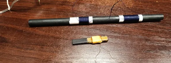
But there is an ancient lifehack from the times of mass use of ferrite antennas: you can take a few more turns, say, 120, divide one coil into two, wind each on a separate paper sleeve, connect them in series, and then slide them along the rod: the greater the total length, the lower the inductance will be.
By moving them along the rod, select the optimal inductance and the best reception quality.
And so, here we go, trying it:
The RC8000 module has four pins: VCC, GND, OUT, and EN.
VCC is 3.3V, OUT is our pulses, EN is enable, which needs to be connected to GND (why? Well, because enable on 0).
Instead of the standard antenna - a homemade Frankenstein.
OUT currently just needs pulses, so we connect a simple LED.
Lifehack: everyone has seen LED strips, including those with 2525 LEDs - small square ones. They are not very durable, some LEDs blacken and burn out, the strips are thrown away and replaced - well, similar LEDs are perfect indicators! They are very sensitive, flashes are clearly visible, and they go well with 3-volt logic. It is precisely such an LED that will be the pulse indicator.
To eliminate interference during tuning - no working ESP nearby, no switching power supplies, two 1.5V batteries.
We turn it on, gradually separate the coils - and here the signal starts.
Once a second - slightly longer, slightly shorter, and then a pause - and the flashes start again once per second.
Done, the DCF77 signal is received, even in the parking lot during the day.
We fix the coils in place - and now we can try connecting this to the ESP.
And a new problem: ESP is interesting because of WiFi, but batteries and WiFi are things that don't mix well.
Of course, you can connect everything through a power supply - but modern switching power supplies are very noisy in the LF band (usually nobody cares, it is hardly used now, but not in this case).
Fortunately, an old transformer power supply was found - the kind that used to come with phones. It turned out to be 12 volts, but here it can be stepped down to 3.3 with a DCDC module - its operating frequency is higher than the DCF77 radio signal, this antenna won't pick it up.
The RC8000 module, together with the antenna, is connected separately; the wire is kept away from the ESP.
It was necessary to connect a capacitor to its VCC and GND, a larger one; without it, it refused to work.
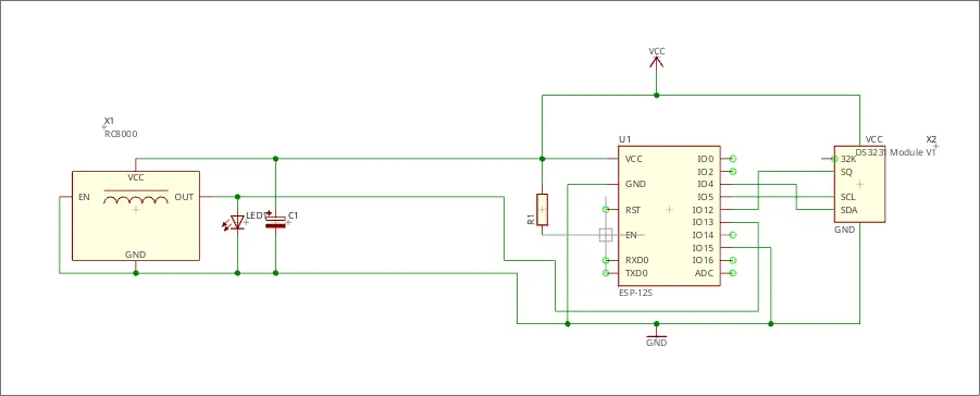
The signal output of the module goes to the ESP input, which is configured to handle interrupts.
The point is that pulses on this input will trigger interrupts: this will mark the rising and falling times of the pulses, allowing the calculation of pulse and pause durations.
Ideally, DCF77 has strict rules: pulses start exactly at the beginning of each minute (atomic clocks, all that stuff), and occur every second except the 59th.
Logical 0 is represented by pulses lasting 100 ms, logical 1 by 200 ms, followed by a pause until the start of the next second, 900 ms and 800 ms respectively.
In practice—there is noise that, even with good reception, slightly distorts pulse timing, making them harder to recognize.
During debugging, it became necessary to analyze the stream of pulse-pause times. Due to limited memory and the need for fast interrupt handling, values had to be divided by powers of two (standard division is slow, but division by 2-4-8 is done by shifting N bits to the right, which is faster).
It turned out this was convenient—it immediately eliminates tiny differences, and pulse analysis then reduces to a few rules:
- if a pause was longer than some value A1—a new pulse starts the minute.
- if a pulse was shorter than some value A2—it was a 0
- if it was longer than A2 but shorter than another value A3—it was a 1
If you divide milliseconds by 2^6 (>> 6) like this and add the character 'A' to the values, the time logs start to look like DNA code (]BNBNDOBNDOBN), and you can simply compare characters: B = 0, D = 1, >Z = start of minute, making it readable by eye from the log.
And everything that doesn't fit this scheme is considered a reception error.
^BOBOBNDMBNDMDMBOBOBNDMDMBOBODMBNBNDMBNBNDMBNBOBNBNBNBNDMDMBNDMBNBODMBNBOB...
This was very helpful during debugging when the signal for some reason wasn't being received (visible in the log—because noise like ACBBCDJ starts appearing, intervals are violated).
Bits are loaded into a 64-bit accumulator (in reverse order, but who cares, it's just more convenient that way). After a pause, A1, the accumulator transfers to the current data, and the collection of new bits begins.
And if there were no explicit errors during the previous collection, the current time is constructed from the data, taking into account the moment the new minute begins (the time of the next minute is always transmitted; it starts with the first pulse after the pause).
The same JbTime library used in the NTP server, with microsecond precision, is used to maintain the resulting time.
And the same NTP distribution library, JbNTP, is used—primarily so that the time can be obtained and compared with other sources.
....
#define INTERRUPT_PIN 13

#define READ_PIN(pin) ((GPIP(pin) ? 1 : 0))

volatile byte int_pulse;                // pulse counter
volatile uint32_t mark_time;            // time mark

volatile uint32_t start_second;         // mark of the start of a new minute
volatile bool set_second;               // flag for readiness to set the minute

volatile bool dcf_ok;                   // current validity

volatile uint64_t dcf_data;             // data for processing
volatile uint64_t dcf_tmp;              // data accumulator

// auxiliary for debugging
volatile byte xlog[180];
volatile byte log_cnt;

// ---------------------------------------------------
void ICACHE_RAM_ATTR run_interrupt(){

  uint32_t tmp = micros();                        // mark microseconds at the start

  uint32_t diff = millis() - mark_time;           // duration of the previous phase
  mark_time = millis();                           // new time mark
  byte sym  = (byte)(diff >> 6) + 'A';            // reduce to a byte

  bool signal = READ_PIN(INTERRUPT_PIN);          // what's there?

  if(signal) {                                    // pulse

    if(sym >= 'Z'){                              // start of a new minute

      start_second = tmp;

      dcf_data = dcf_tmp;                         // dump old buffer
      dcf_tmp = 0;                                // clear buffer

      set_second = false;
      if(dcf_ok && int_pulse == 58)
        set_second = true;                        // previous second is counted

      dcf_ok = true;                              // consider OK
      int_pulse = 0;                              // bit counter
      log_cnt = 0;

    }
    else{
      int_pulse ++;
      // can try to check for parity match
      // correct pauses - M,N,O, with BN, BO and DN, DM being more correct
      // but can be skipped
    }
  }else{

    if(sym == 'B'){
      // this is 0
    }
    else if(sym == 'D' ){
      // this is 1
      dcf_tmp |= (uint64_t)(0x1ULL << int_pulse );
    }
    else {
      // this is garbage
      dcf_ok = false;
    }
  }

  // for debugging
  xlog[ log_cnt ] = sym;
  log_cnt ++;
  if(log_cnt > 170) log_cnt = 0;

}

// ---------------------------------------------------
void PulseSetup(){
  int_pulse = 0;
  mark_time = 0;
  dcf_data = 0;
  dcf_tmp = 0;
  set_second = false;
  dcf_ok = false;

  // for debugging
  log_cnt = 0;
  memset((void*)xlog,0,sizeof(xlog));

  pinMode(INTERRUPT_PIN, INPUT);
  attachInterrupt(digitalPinToInterrupt(INTERRUPT_PIN),run_interrupt,CHANGE);

}

byte dcf_weights[] = {1,2,4,8,10,20,40,80};
#define CEST_OFFSET 3600*2
#define CET_OFFSET  3600

#include

// ---------------------------------------
void PulseLoop(){

  if(set_second){

    // example
    // 0100011100011000010011100110000001011000010100010101100100100000
    // 0000110111110100010010100000110001001000010100010001100100100000
    if(dcf_data & 1ULL) return;                 // must be 0
    if(! (dcf_data & (1ULL << 20)) ) return;    // must be 1


    bool sum = 0;
    // minute
    int minute = 0;
    for(int i = 21; i < 28; i++){
      if(dcf_data & (1ULL << i )){
        minute += dcf_weights[i - 21];
        sum = !sum;
      }
    }
    if((bool)(dcf_data & (1ULL << 28 )) != sum) return;
    // hour
    sum = 0;
    int hour = 0;
    for(int i = 29; i < 35; i++){
      if(dcf_data & (1ULL << i )){
        hour += dcf_weights[i - 29];
        sum = !sum;
      }
    }
    if((bool)(dcf_data & (1ULL << 35 )) != sum) return;
    // date
    sum = 0;
    int mday = 0;
    for(int i = 36; i < 42; i++){
      if(dcf_data & (1ULL << i )){
        mday += dcf_weights[i - 36];
        sum = !sum;
      }
    }
    int wday = 0;
    for(int i = 42; i < 45; i++){
      if(dcf_data & (1ULL << i )){
        wday += dcf_weights[i - 42];
        sum = !sum;
      }
    }
    int month = 0;
    for(int i = 45; i < 50; i++){
      if(dcf_data & (1ULL << i )){
        month += dcf_weights[i - 45];
        sum = !sum;
      }
    }
    int year = 2000;
    for(int i = 50; i < 58; i++){
      if(dcf_data & (1ULL << i )){
        year += dcf_weights[i - 50];
        sum = !sum;
      }
    }
    if((bool)(dcf_data & (1ULL << 58 )) != sum) return;

    DateTime now = DateTime(year, month, mday, hour, minute, 0);
    unsigned long dtm = now.unixtime();

    bool cest = dcf_data & (1ULL << 17);
    bool cet = dcf_data & (1ULL << 18);
    if (cest && !cet){
      dtm -= CEST_OFFSET;
    }
    else if (!cest && cet){
      dtm -= CET_OFFSET;
    }
    else return;

    uint32_t usec = micros() - start_second;

    systime.settime(dtm, usec);
    systime.fresh = true;

    if(systime.fresh){
      if(RTCSetTime(&systime)){
        systime.fresh = false;
      }
    }

    set_second = false;
  }
}
// ---------------------------------------
void setup(){
  ...

  PulseSetup();

  NTPSetup();

  ...
}

void loop(){
  ...

  PulseLoop();

  NTPLoop();

  ...
}
The RTC module is connected in the same way as there.
The only difference is that the sole time source will be DCF77.
And now - I'm testing the result:
/sbin/ntpdate -d 192.168.1.49
ntpdig: querying 192.168.1.49 (192.168.1.49)
org t1: ed92223c.60d05000 rec t2: ed92223c.9f7af640
xmt t3: ed92223c.9f7af640 dst t4: ed92223c.aecb0000
org t1: 1776788412.378179 rec t2: 1776788412.622970
xmt t3: 1776788412.622970 dst t4: 1776788412.682785
rec-org t21: 0.244792  xmt-dst t34: -0.059815
2026-04-21 19:20:12.622970 (+0300) +0.092488 +/- 0.152309 192.168.1.49 s1 no-leap
Not bad (0.092488 - deviation from previously set), considering that the time is taken literally out of thin air.
We can put the device to work...
But there are also downsides: for example, a regular drill-driver nearby drives the device crazy, the indicator blinks like crazy.
In general, this is something that should work for a long time, slowly, in the countryside, gradually synchronizing as if by itself.



Write comment