- Hardware
- A
Details of the Fnirsi DPS-150 power supply control protocol
In the previous article, I began to analyze the control protocol of the Fnirsi DPS-150 power supply. The packet format was analyzed, commands and responses to them were identified, and a draft analysis of the internals of the proprietary control program was made. I promised to show the details of the process later. Well, that time has come. Today we will get command and response tables as complete as required for real work.
Sequence of Analysis
So, we study the program using the .Net Reflector decompiler. When studying the program, it is very desirable to go sequentially. For example, first study the commands, then the responses. Or vice versa, first the responses, then the commands. But the main thing is to go sequentially. Alas! When "digging" with missing debug information, this will not work. We will always come across something incomprehensible. And in such situations, it is very important not to try to break through a brick wall, otherwise you can first lose a lot of time, and then lose interest in the topic altogether.
Can't understand the command? No problem! Let's move on to the next one. Too many incomprehensible commands? Again, no problem, let's look at the responses. In addition to the strings in the program, we also check the logs of the analyzer. Sometimes they help too. For example, we see such a fragment in the log when opening the block with the proprietary program:
...are found only in this context:
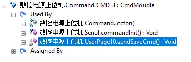
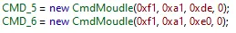
The first link is filling its body, the second link just shows that the command is sent during the connection initialization among other commands:
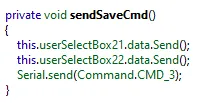
What are UserSelectBox21 and UserSelectBox22? Here they are!
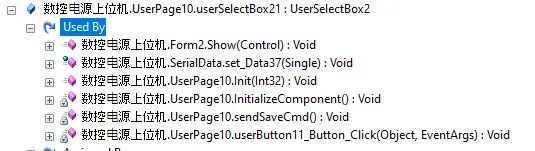
We already know that the juiciest result is given by the InitializeComponent() function. Let's go to it and see which dialog we are in.
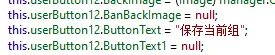
Which translates to "Save current group".
Looking around, where do we have groups in the program... Here they are!
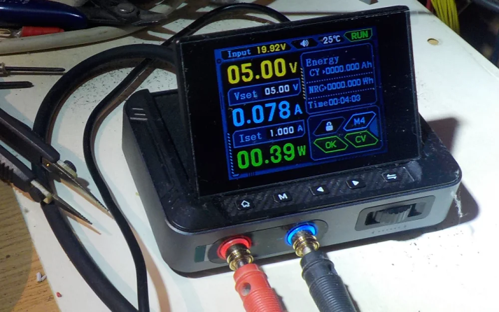
We enter, say, group 5, and see there:
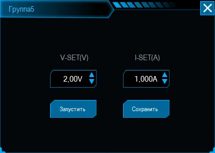
We click "Save", and catch such commands in the log:

Here is the third command in the sequence — exactly the same COMMAND_3, the code of which in the log is 0xff. What does it do? And what kind of sheet does it return in response? Let's gradually move on to it.
All data from the device at once
So, when the device is opened, the COMMAND_3 command is sent, to which a simply huge response comes:
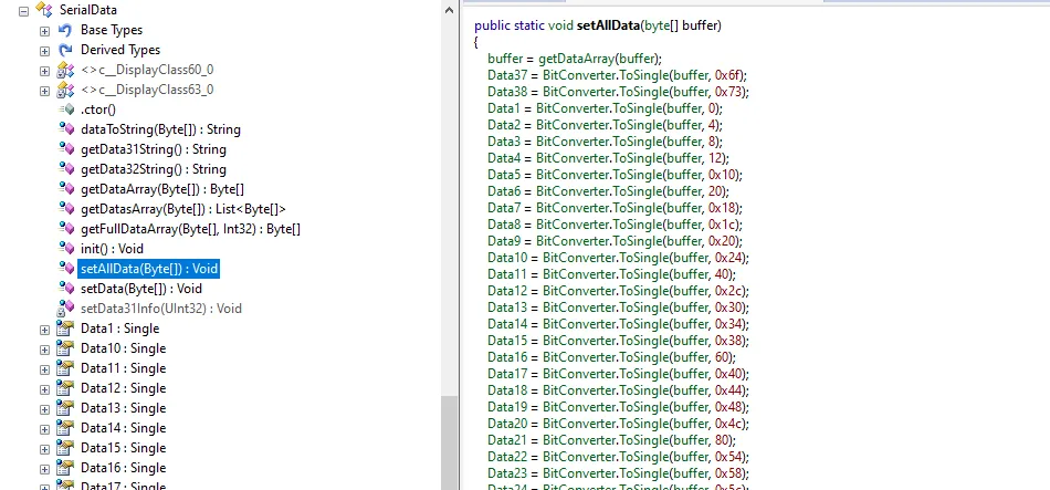
0x8c bytes came in the dump. The code that parses this is simply huge. In the new editor, I had trouble hiding it under the cut, so I'll just give the beginning. Those who are really interested will see the full version when they open everything in Reflector themselves.
public static void setAllData(byte[] buffer)
{
    buffer = getDataArray(buffer);
    Data37 = BitConverter.ToSingle(buffer, 0x6f);
    Data38 = BitConverter.ToSingle(buffer, 0x73);
    Data1 = BitConverter.ToSingle(buffer, 0);
    Data2 = BitConverter.ToSingle(buffer, 4);
    Data3 = BitConverter.ToSingle(buffer, 8);
    Data4 = BitConverter.ToSingle(buffer, 12);
    ...
    Data41 = BitConverter.ToSingle(buffer, 0x7f);
    Data42 = BitConverter.ToSingle(buffer, 0x83);
    Data43 = BitConverter.ToSingle(buffer, 0x87);
}
It analyzes just about 0x8c bytes (to be exact, 0x8b, but the dump clearly has an alignment correction). So let's assume that these are the fields.
After minimal comparison, we find that this is indeed the case. In fact, the program uses some of the fields from here as the contents of the EEPROM. We saw above how voltages and currents are saved for groups. And to load them, this command is used. In the operation of its problem-oriented program, it is not particularly needed. But we figured it out. If the purpose of the command is unknown... What if it is vital? Now it is clear that there is no point in digging deeper.
Block addressing
I think this article will be read for two reasons:
1) she was recently published, so the reader just found her in the list;
2) months or years later, someone typed the power supply model into a search engine to find a description of the protocol.
In the first case, the reader will not go into the smallest details. He needs to be shown how the protocol is opened, but not with the accuracy of every nook and cranny of the code. Someone will simply scroll through the general features like a detective, someone may even consolidate the skill by finding the program on the manufacturer's website Fnirsi. The other day she moved to their Software section, for some reason she used to lie around like Firmware. But again, no one will remember and go through all the little things for a block that he does not have and is unlikely to have. General skills are needed. And there is no point in going down to the smallest details.
And whoever came for the data, he is already shaking with indignation: "I will not try all this, give me the command tables!".
So let me show you another interesting thing, and I'll wrap up the parsing process. I'll try to speculate about device addressing.
In general, you can select the block address in the program:
Just before closing the port, you should send:
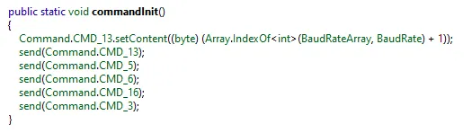
The initialization sequence looks like this:
Responses
The response table looks like this:
Code | Name | Type | Purpose |
0xc0 | Data1 | float | Input voltage |
0xc3 | Data4 Data5 Data6 | float float float | Active voltage Active current Active power |
0xc4 | Data7 | float | Temperature |
0xd9 | Data28 | float | A*h (I think the parameter is translated incorrectly) |
0xda | Data29 | Float | W*h (I think the parameter is translated incorrectly) |
0xdb | Data30 | uint8 | Output state (open or closed) |
0xdc | Data31 | uint8 | LED NORM (no fault) |
0xdd | Data32 | uint8 | Voltage stabilization (01) or current (00) |
0xde | Data33 | String | Model |
0xdf | Data34 | String | Usage not found |
0xe0 | Data35 | string | Firmware version |
0xe1 | Data36 | uint8 | Some index, it is not yet clear which one. Is it the device address? Until it runs in the air, we do not try to send any commands. If it has not been there for a long time, we disconnect |
0xe2 | Data37 | float | Upper voltage limit that can be requested (input minus drop on the stabilizer) |
0xe3 | Data38 | float | Upper current limit that can be set |
0xff | - | - | All data in bulk |
Conclusion
We got acquainted with advanced methods of protocol analysis using the example of the Fnirsi DPS-150 power supply. The information provided is sufficient to develop your own program to control the unit.
The program developed by the author is very specific, so it will not be presented in its pure form, but there are plans to make an article explaining an interesting technology using this protocol as an example. There will be real code. Of course, if the topic is of interest to the reader.

![From Virtual Hands to AI for Survivalists: Curious Open Agent OSes [and One Hardware Project]](https://cdn.tekkix.com/imgs/2026/05/habrcom/big/ce0b1057616faed51cd8b9f3b2b9.webp)

Write comment