- Hardware
- A
Lily58 Pro Split Keyboard: How I Made It Wireless. Soldering, GitHub, and Batteries
Recently, I published an article here about the wireless Sofle RGB keyboard. Overall, it works well with no glitches, except for minor issues. The only thing is that I prefer low-profile keyboards more. I realized this when I returned to the Lily58 Pro after a couple of days working on the Sofle RGB. I had gotten so used to it that it was hard to adjust. However, upon returning, one thing started to annoy me—wires.
The cable to the computer and the cord between the halves worked flawlessly, but first of all, these are unnecessary elements on the desk. Secondly, they limit mobility. Moving the laptop, connecting a second PC, spreading the halves wider — and I had to think about the length of the cable again. In short, I decided to make it wireless. To preemptively say, it worked out. This article, by the way, is written using the Lily58 Pro. But there were many interesting things that I will discuss below. Let’s go!
Controllers and New Architecture
The wired Lily58 uses a Pro Micro with QMK — it's a controller designed for power and data transfer via USB. Here it's simple: key presses are read and processed, and that’s it. In the wireless configuration, the requirements are different. The controller must also support battery operation and provide a wireless connection. In short, microcontrollers needed to be changed. It turned out to be quite straightforward.
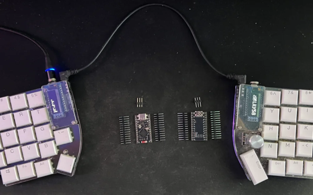
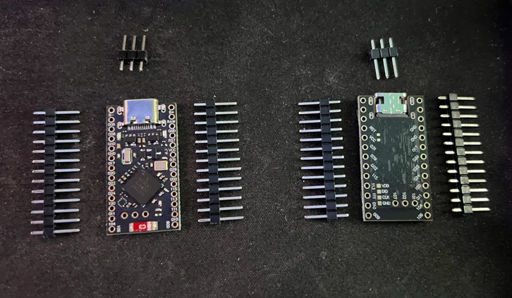
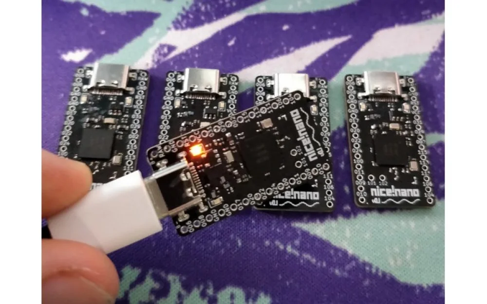
I bought two controllers on nRF52840 from Amazon — one for each half. They cost 7 euros each, which is very inexpensive. The form factor and pinout are compatible with nice!nano v2. This, by the way, is a key point: the Lily58 Pro is designed for Pro Micro, and these boards replicate the same footprint and pitch of the pins. They just fit into the sockets. No matrix modifications or adapters are required. Just keep in mind that the wireless modules have two extra contacts for battery power.
The hardware is quite good: ARM Cortex-M4F 64 MHz, 1 MB of flash, and 256 KB of RAM. For a wired keyboard, such resources would seem excessive. In the wireless version, they are appropriate. Here, Bluetooth, half synchronization, layer processing, macros, and power-saving logic all work simultaneously. When there is enough memory, everything works smoothly.
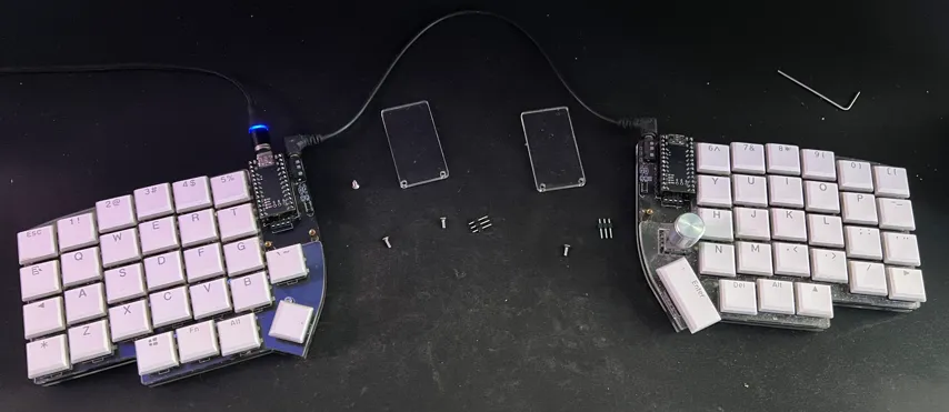
Separately about the power supply. Controllers of this format are already designed for Li-Po 3.7 V, and charging is done via USB. The battery connects directly, so there's no need to build anything additional. Accordingly, the case has no extra boards or wires — just the controller and the battery.
Flashing controllers: from board to full keyboard
In a wireless split keyboard, flashing is the stage that transforms a bare controller (nice!nano or any other based on nRF52840) into a working device. Without it, the board remains just a piece of metal with a chip: the system won't recognize it as a keyboard, and the layout and all the logic simply won’t work.
And here I was met with a pleasant surprise. Specifically, a built-in bootloader that makes the flashing process as simple as possible. No external programmers, wires to SWD pins, or special utilities are needed. The controller appears in the system as a regular removable USB drive. Thank you to the developers.
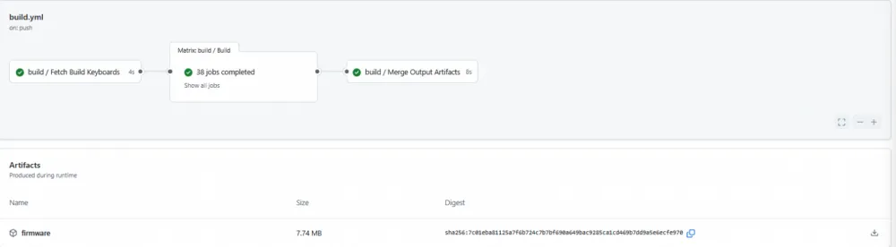
Since the keyboard consists of two independent halves, the firmware for each of them is built separately. In ZMK, this involves two .uf2 format files — one for the left half (typically called left.uf2), and the other for the right (right.uf2). I compiled them using GitHub Actions: I configured the workflow for my setup and received two ready artifacts as output. This is convenient and fast — there's no need to maintain a local environment with a bunch of dependencies.
The main source of errors for beginners is mixing up the files during flashing. As they say, one mistake — and you're wrong. If something goes wrong, you’ll receive a mirrored layout or even a non-working half.
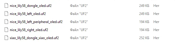
At first, the config had more options than necessary: options for other boards, dongles, alternative builds. I didn't need any of this, so in build.yaml, I kept only the two configurations I needed.
Updating the firmware is very simple, almost like copying a file to a flash drive. You take the half of the keyboard you want to flash, double-tap the Reset button on the controller, and the board enters bootloader mode. It appears in the system as a USB drive with a name like NICENANO or NRF52BOOT. You open this "disk" and simply drag the required .uf2 file into it. Once the copy is complete, the controller automatically reboots, the "disk" disappears, and the board starts up with the new firmware.
After successfully loading both halves, the keyboard switches to ZMK operational mode. The left half automatically becomes the central part and connects directly to the computer or phone via Bluetooth, while the right half connects to the left as a peripheral.
If you need to clear old Bluetooth pairings (for example, when changing devices or if there's no connection), this is done with a separate key combination specified in your layout. Alternatively, if nothing is specified, you need to load a special configuration file onto both halves. It overwrites the flash memory and resets all settings. After that, you need to load the firmware files.
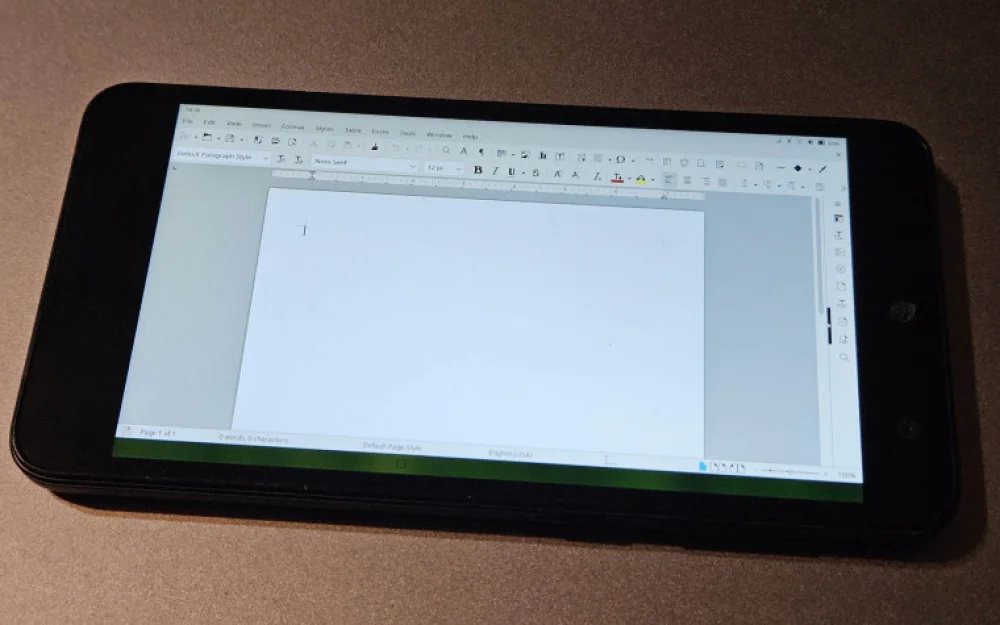
What about the layout
There are many possibilities. You can customize your own either directly on GitHub with subsequent firmware updates or through the ZMK Studio tool (there's a desktop and a web version). The connection works without problems (the firmware should have ZMK support specified), after which everything can be changed "on the fly." The results are saved in flash memory.
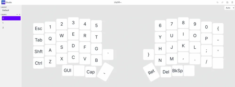
The logic of the layout in ZMK is built around layers. There is a base layer — the one where regular text input occurs. It is active by default and is perceived as the "main" keyboard. All other layers are overlaid on top of it and temporarily or permanently change the behavior of the keys.
Additional layers can be activated in different ways: by holding a specific key, toggling once, or using a combination. They usually display numbers, symbols, text navigation, volume control, and playback, system commands. This approach allows for not inflating the physical keyboard but logically redistributing functions.
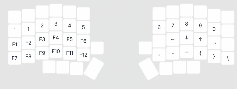
For a compact split keyboard, this is especially important. There are fewer keys than on a full-sized keyboard, so the layers effectively compensate for the lack of "hardware." The same button can perform completely different tasks depending on the active layer — from inputting a character to controlling the cursor.
A separate level of flexibility is added by the contextual behavior of the keys. A short press and a hold can be interpreted differently: for example, a quick press types a letter, while holding acts as a modifier. As a result, the layout stops being a static scheme and turns into a tool that adapts to the typing style and habits of the owner. In short, there are a million possibilities, and it can be configured for months. The main thing is to remember to save everything, so it won't be painfully difficult later.
Testing!
An important note — batteries are needed, and not just any, but specifically 3.7V, miniaturized ones. After all, they need to be placed somewhere in the case, right? For the initial tests, I used what I had on hand: one battery from an old fitness tracker and another from a wireless headset. I initially understood that there could be problems with them and only used them to check the overall functionality of the keyboard — to ensure that everything powers on, flashes, and connects. I wasn't counting on long-term stable operation.
Outwardly, the components looked functional, but that was only on the surface. During operation, problems arose. The old components discharged literally within half an hour of active typing. But that didn't bother me. The main thing was that the keyboard worked.
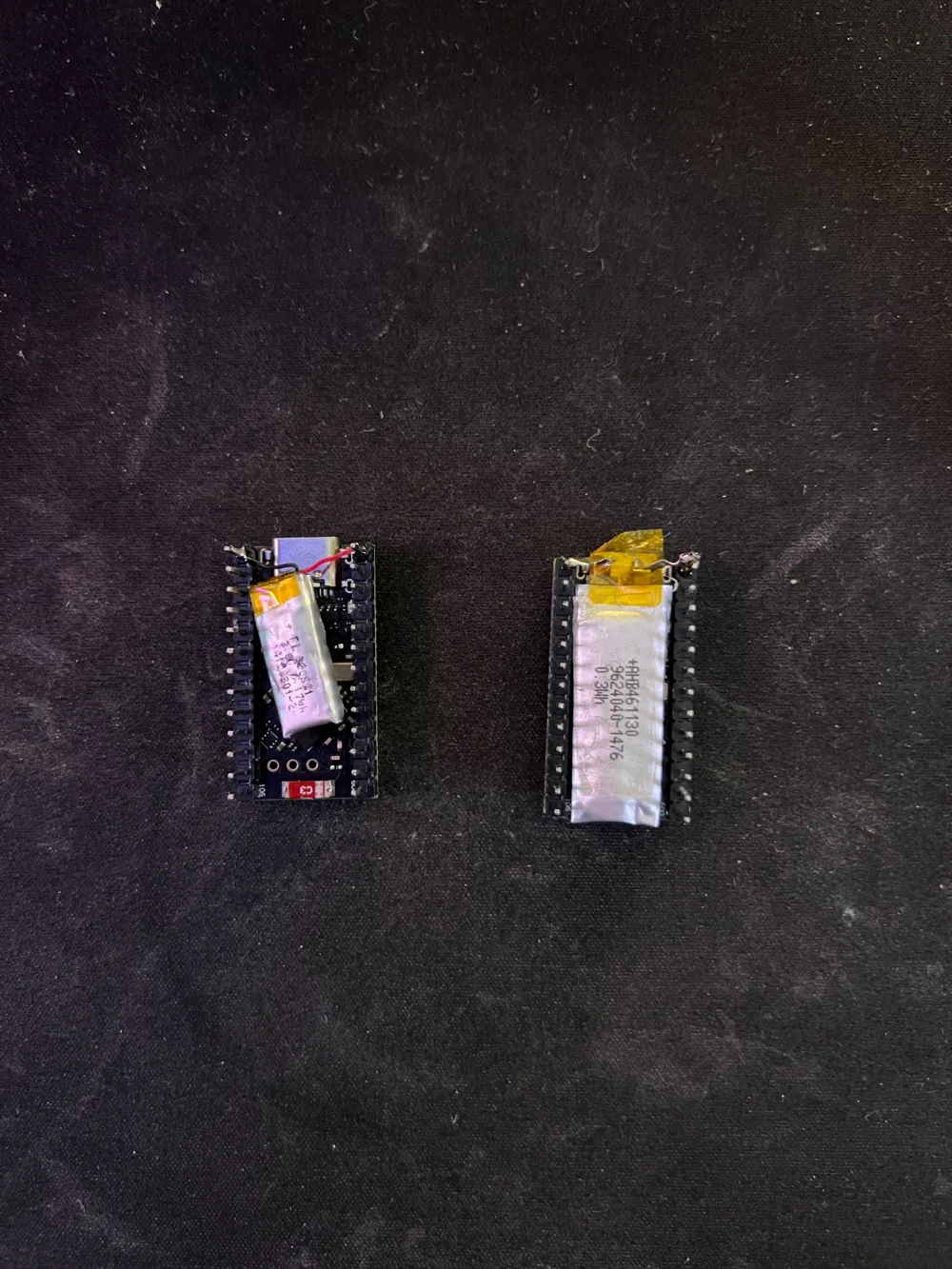
After the test, I ordered brand new power elements. For my build, I chose 301230 format batteries — lithium-polymer cells at 3.7 V with a capacity of 80 mAh. The numbers in the name indicate the dimensions: approximately 30 × 12 × 3 mm. The batteries are very thin and light, easily fitting inside the case of the split keyboard and requiring no modifications to the design. They hold about 0.3 Wh of energy — a small amount, but typical for compact electronics.
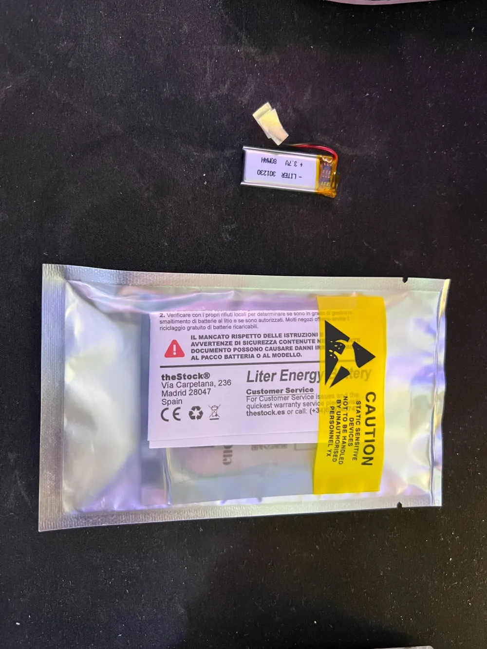
They are inexpensive — around 20 euros for two, ordered from Amazon. A nice touch: they come with wires already soldered on, and the contacts are neatly insulated. So there's no need to solder anything to the cell itself. I connected it to the board — and can now test the autonomous operation.
Of course, I understand that 80 mAh is a small reserve. It was important to achieve autonomy for at least a day and have the ability to place the batteries in the gap between the bottom part of the case and the board.
There were no issues here, as the thickness of the battery is only 3 mm, which easily allows it to be installed wherever desired. I'm currently testing the autonomy. If it's not enough, I will order higher-capacity ones, but then I'll have to print a case for the keyboard with a "pocket" for the battery on a 3D printer.
Results and Future Plans
After installing the new batteries, updating the ZMK base, and simplifying the configuration, the keyboard finally entered a mode that can be described with the words "just works." BLE is stable, discharge is smooth, and the split connects to the PC without problems.
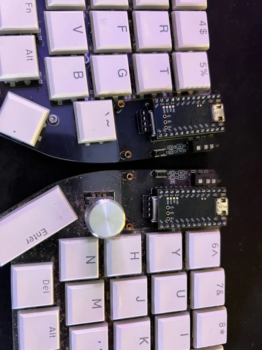
Plans include adding addressable backlighting for each key. Here, I need to figure out the power supply and consumption control to avoid surprises. But I think I can handle it. Additionally, I want to restore volume control via the encoder on the right half, correctly configuring the overlay and A/B pins. This was very convenient.
By the way, the backlighting can be controlled from the keyboard. Layer configuration allows for organizing quite complex scenarios. But that's for the near future; for now, that's all. Stay tuned, there will be more interesting content ahead!

![From Virtual Hands to AI for Survivalists: Curious Open Agent OSes [and One Hardware Project]](https://cdn.tekkix.com/imgs/2026/05/habrcom/big/ce0b1057616faed51cd8b9f3b2b9.webp)

Write comment