- Network
- A
Simulating Networks in GNS3. Part 3 - Cisco, VLAN
This article describes the practical transition from physical to logical network segmentation using the example of a small business network with three buildings.
Hello, my name is Nikita Rukavkov and I am the author of the channel DevOps Brain. In this series, we continue to explore the capabilities of GNS3 and study network theory in practice.
Our network scheme is already good, but it does not scale well. To simplify understanding of the problem, let's imagine that this is a network of a small enterprise, which has 3 buildings: LAN1 is the 1st building, LAN2 is the 2nd, and LAN3 is the 3rd (ZONE1-3 respectively).
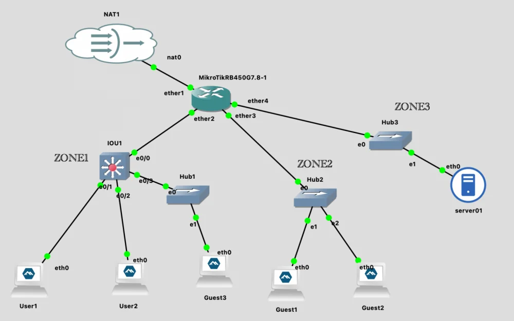
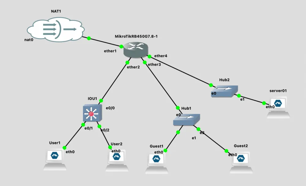
Currently, our scheme looks like this:
ether2 = LAN1 (employees)
ether3 = LAN2 (guests)
ether4 = LAN3 (servers)
Let's assume that in the 2nd building there is no longer enough space for guests. And in the first building, there is free open space and a lot of free area. As a result of discussions among the enterprise leaders, it was decided to organize guest access in this open space.
You thought a bit and realized that with the current scheme you are very limited, and even if it's possible to organize guest access (let me remind you that the guest network only has access to the Internet), you will have to start cobbling together solutions on Mikrotik. So you decided that it would be better to switch from physical segmentation of the network to logical segmentation while there's still time.
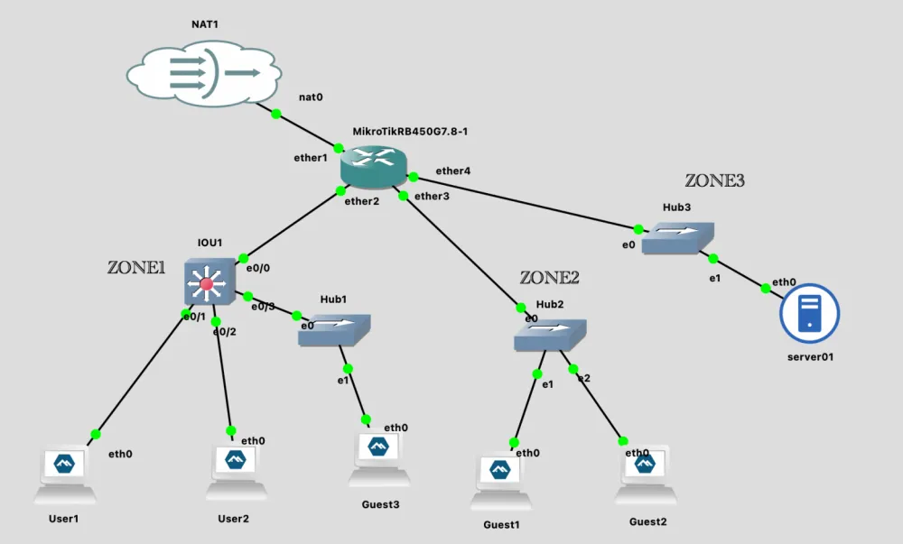
The new scheme:
ether2 = TRUNK
  ├─ VLAN10 (LAN1 – employees)
  ├─ VLAN20 (LAN2 – guests)
ether3 = VLAN20 (LAN2 – guests)
ether4 = VLAN30 (LAN3 - servers)
Switching to Cisco IOU L2 switch
Now we need to on the switch port that connects to Mikrotik, create a trunk with VLAN (10,20). And for those connected to end devices, assign the appropriate VLAN. And we will … not be able to do this using Network Switch. This is due to certain limitations.
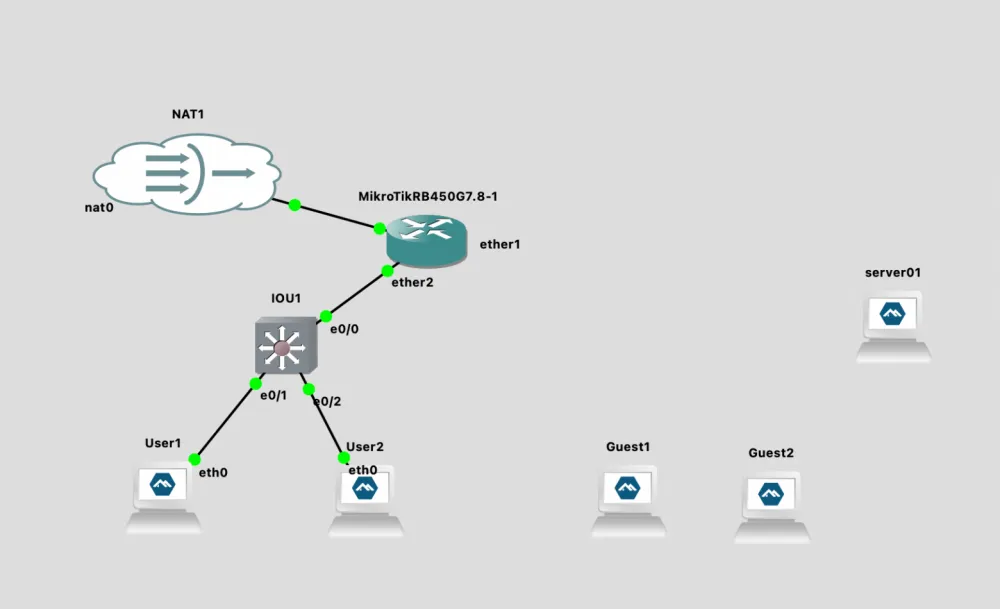
Therefore, let's replace Ethernet Switch with Cisco IOU L2 15.2d. And at the same time, let's remove the remaining Network Switch - they will no longer be needed. Later, we will replace them with Ethernet Hub.
As usual, through New Template, we will add the switch Cisco IOU L2 15.2d.
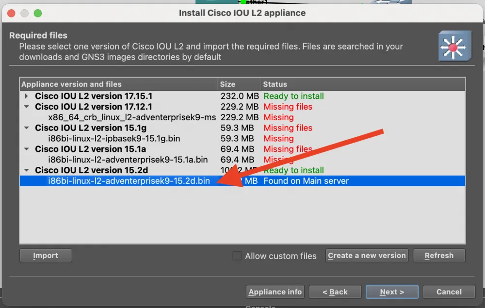
But there will be no Download button here, and you will not be able to download the image. Look for the image i86bi-linux-l2-adventerprisek9-15.2d.bin on the Internet. Don't worry about downloading a file from an unofficial site - when importing, GNS3 will check the checksum and warn you if something is wrong.
When working with Cisco, there will be another nuance - IOU License. It will need to be generated on the server with GNS3. So let’s connect to it via ssh, after searching for a license generator on github.
gns3@gns3vm:~$ curl -o keygen.py
% Total % Received % Xferd Average Speed Time Time Time Current
Dload Upload Total Spent Left Speed
100 1056 100 1056 0 0 5360 0 --:--:-- --:--:-- --:--:-- 5360
gns3@gns3vm:~$ python3 keygen.py
*********************************************************************
Cisco IOU License Generator - Kal 2011, python port of 2006 C version
Modified to work with python3 by c_d 2014
hostid=00000000, hostname=gns3vm, ioukey=25e
Add the following text to ~/.iourc:
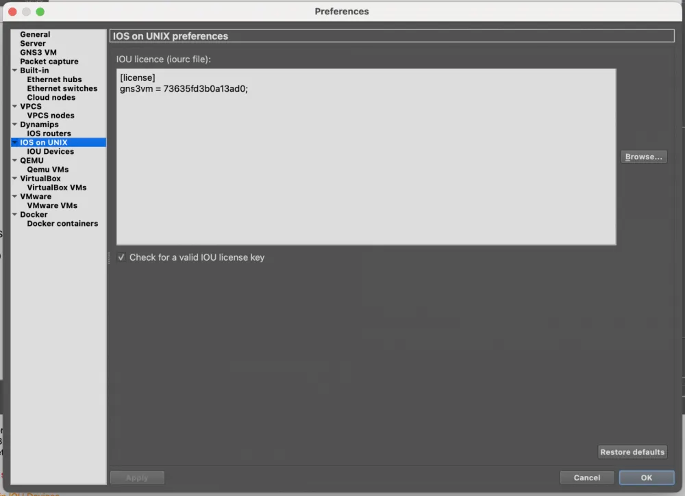
**[license]
gns3vm = 73635fd3b0a13ad0;**
You can disable the phone home feature with something like:
echo '127.0.0.127 xml.cisco.com' >> /etc/hosts
And we specify in the IOS on UNIX settings.
We connect to the Cisco console and enter the configuration below
**IOU1#conf t**
vlan 10
name LAN10
vlan 20
name LAN20
end

IOU1#show vlan brief

VLAN Name                             Status    Ports
---- -------------------------------- --------- -------------------------------
1    default                          active    Et0/0, Et0/1, Et0/2, Et0/3
                                                Et1/0, Et1/1, Et1/2, Et1/3
                                                Et2/0, Et2/1, Et2/2, Et2/3
                                                Et3/0, Et3/1, Et3/2, Et3/3
10   LAN10                            active
20   LAN20                            active
1002 fddi-default                     act/unsup
1003 token-ring-default               act/unsup
1004 fddinet-default                  act/unsup
1005 trnet-default                    act/unsup

**IOU1#conf t**
interface Ethernet0/0
switchport trunk encapsulation dot1q
switchport mode trunk
switchport trunk allowed vlan 10,20
no shutdown
end

**IOU1#show interfaces trunk**
Port        Mode             Encapsulation  Status        Native vlan
Et0/0       on               802.1q         trunking      1
Port        Vlans allowed on trunk
Et0/0       10,20
Port        Vlans allowed and active in management domain
Et0/0       10,20
Port        Vlans in spanning tree forwarding state and not pruned
Et0/0       none

**IOU1#conf t**
interface Ethernet0/1
switchport mode access
switchport access vlan 10
no shutdown
end

**IOU1#conf t**
interface Ethernet0/2
switchport mode access
switchport access vlan 10
no shutdown
end

**IOU1#show vlan brief**

VLAN Name                             Status    Ports
---- -------------------------------- --------- -------------------------------
1    default                          active    Et0/3, Et1/0, Et1/1, Et1/2
                                                Et1/3, Et2/0, Et2/1, Et2/2
                                                Et2/3, Et3/0, Et3/1, Et3/2
                                                Et3/3
10   LAN10                            active    Et0/1, Et0/2
20   LAN20                            active
1002 fddi-default                     act/unsup
1003 token-ring-default               act/unsup
1004 fddinet-default                  act/unsup
1005 trnet-default                    act/unsup

**IOU1#show interfaces switchport**
Name: Et0/0
Switchport: Enabled
Administrative Mode: trunk
Operational Mode: trunk
Administrative Trunking Encapsulation: dot1q
Operational Trunking Encapsulation: dot1q
Negotiation of Trunking: On
Access Mode VLAN: 1 (default)
Trunking Native Mode VLAN: 1 (default)
Administrative Native VLAN tagging: enabled
Voice VLAN: none
Administrative private-vlan host-association: none
Administrative private-vlan mapping: none
Administrative private-vlan trunk native VLAN: none
Administrative private-vlan trunk Native VLAN tagging: enabled
Administrative private-vlan trunk encapsulation: dot1q
Administrative private-vlan trunk normal VLANs: none
Administrative private-vlan trunk associations: none
Administrative private-vlan trunk mappings: none
Operational private-vlan: none
Trunking VLANs Enabled: 10,20
Pruning VLANs Enabled: 2-1001
Capture Mode Disabled
...

IOU1#show interfaces trunk
Port        Mode             Encapsulation  Status        Native vlan
Et0/0       on               802.1q         trunking      1
Port        Vlans allowed on trunk
Et0/0       10,20
Port        Vlans allowed and active in management domain
Et0/0       10,20
Port        Vlans in spanning tree forwarding state and not pruned
Et0/0       10,20

**IOU1#write memory**
Everything looks exactly as we intended: Et0/0 is the trunk for VLAN 10 and 20. And Et0/1 and Et0/2 are ports with VLAN 10.
Here, an attentive reader may wonder: why are we configuring VLAN 20 at all? The fact is that I wanted to demonstrate the power of VLANs. Remember at the beginning of the article I asked you to imagine that LAN1, LAN2, and LAN3 are different buildings.
Creating a bridge and setting up VLAN interfaces
Now we will replace the remaining Ethernet Switch with an Ethernet Hub and connect the network interfaces. A hub is an unmanaged device that simply retransmits all frames. This is good for demonstrating that end devices are unaware of VLANs.
Now we can move on to configuring Mikrotik.
# Let's see what's going on with the IP addresses now
[admin@MikroTik] /ip/dhcp-server> /ip address print
Flags: D - DYNAMIC
Columns: ADDRESS, NETWORK, INTERFACE
#   ADDRESS            NETWORK        INTERFACE
0   192.168.10.1/24    192.168.10.0   ether2
1   192.168.20.1/24    192.168.20.0   ether3
2 D 192.168.122.83/24  192.168.122.0  ether1
3   192.168.30.1/24    192.168.30.0   ether4

# First, we remove old IPs from physical interfaces
/ip address remove [find interface=ether2]
/ip address remove [find interface=ether3]
/ip address remove [find interface=ether4]

# Bridge is a virtual L2 switch inside MikroTik.
# It combines physical ports (ether2-ether4) into a single logical switch.
# vlan-filtering=yes - we enable VLAN filtering. Without it, VLANs will not work!
# IMPORTANT: The bridge ITSELF does NOT get an IP address. IPs will be on VLAN interfaces.
/interface bridge add name=br-lan vlan-filtering=yes

# Adding physical ports to the bridge
# This is analogous to connecting cables to switch ports
/interface bridge port
# ether2 - trunk port to Cisco. It will pass TAGGED frames (with VLAN tags 10,20)
# PVID=1 by default: untagged traffic will be considered VLAN 1
add bridge=br-lan interface=ether2

# ether3 - access port for VLAN 20 (guests)
# PVID=20: all untagged traffic from this port is automatically marked as VLAN 20
# Devices connected here do NOT know about VLAN - they just send regular frames
add bridge=br-lan interface=ether3 pvid=20

# ether4 - access port for VLAN 30 (servers)
# PVID=30: all untagged traffic from this port is automatically marked as VLAN 30
add bridge=br-lan interface=ether4 pvid=30

# Creating VLAN interfaces on the bridge
# These are L3 (network) interfaces for routing between VLANs
# Each VLAN interface operates on a specific VLAN ID over the bridge
/interface vlan
# vlan10-users: logical interface for VLAN 10
# vlan-id=10: listens/sends frames with VLAN tag 10
# interface=br-lan: operates over our bridge
# We will later assign IP 192.168.10.1/24 to this interface
add name=vlan10-users vlan-id=10 interface=br-lan

# vlan20-guests: logical interface for VLAN 20
# vlan-id=20: listens/sends frames with VLAN tag 20
# We will assign IP 192.168.20.1/24 to this interface
add name=vlan20-guests vlan-id=20 interface=br-lan

# vlan30-servers: logical interface for VLAN 30
# vlan-id=30: listens/sends frames with VLAN tag 30
# We will assign IP 192.168.30.1/24 to this interface
add name=vlan30-servers vlan-id=30 interface=br-lan

# Assigning IP addresses (L3)
/ip address
add address=192.168.10.1/24 interface=vlan10-users
add address=192.168.20.1/24 interface=vlan20-guests
add address=192.168.30.1/24 interface=vlan30-servers

# Checking the routing table
[admin@MikroTik] /interface/bridge/vlan> /ip route print
Flags: D - DYNAMIC; A - ACTIVE; c, d, y - COPY
Columns: DST-ADDRESS, GATEWAY, DISTANCE
    DST-ADDRESS       GATEWAY         DISTANCE
DAd 0.0.0.0/0         192.168.122.1          1
DAc 192.168.10.0/24   vlan10-users           0
DAc 192.168.20.0/24   vlan20-guests          0
DAc 192.168.30.0/24   vlan30-servers         0
DAc 192.168.122.0/24  ether1                 0

# Changing DHCP server interfaces to VLAN interfaces
/ip dhcp-server
set dhcp_lan1 interface=vlan10-users
set dhcp_lan2 interface=vlan20-guests
set dhcp_lan3 interface=vlan30-servers

# The DHCP servers remain the same
[admin@MikroTik] /ip/dhcp-server> /ip dhcp-server network print
Columns: ADDRESS, GATEWAY, DNS-SERVER
# ADDRESS          GATEWAY       DNS-SERVER
0 192.168.10.0/24  192.168.10.1  192.168.10.1
1 192.168.20.0/24  192.168.20.1  192.168.20.1
2 192.168.30.0/24  192.168.30.1  192.168.30.1
Guest Access in Openspace
So, we connected a brand new L2 Cisco switch. The old users from LAN1 are happy - we have restored their Internet
During the work process, there was a requirement to organize an isolated network in the building with LAN1 that has the same rights as LAN2. That is, only with access to the internet and nowhere else. No problem - we add a switch and configure the port on the Cisco switch Ethernet0/3 and set vlan 20 on it. Since we have taken care in advance that VLAN 20 can be in the trunk - we just need to configure it on the port Ethernet0/3.
IOU1#conf t
Enter configuration commands, one per line.  End with CNTL/Z.
IOU1(config)#interface Ethernet0/3
IOU1(config-if)#switchport mode access
IOU1(config-if)#switchport access vlan 20
IOU1(config-if)#no shutdown
IOU1(config-if)#end
And now, despite the fact that our Guests are located in the first building, they receive IP addresses for VLAN2 and all firewall rules on the Mikrotik router apply to them. Nothing additional needs to be configured.
You can independently check the issued IP addresses, accessibility within and between zones. And if you have done this - you will see that clients in Zone 2 and Zone 3 did not receive IP addresses. The problem is that clients cannot assign tags themselves, and we need to tell Mikrotik to assign them automatically.
[admin@MikroTik] /ip/address> /interface bridge port add bridge=br-lan interface=ether3 pvid=20
[admin@MikroTik] /ip/address> /interface bridge port add bridge=br-lan interface=ether4 pvid=30
[admin@MikroTik] /ip/address> /interface bridge port print
Columns: INTERFACE, BRIDGE, HW, PVID, PRIORITY, PATH-COST, INTERNAL-PATH-COST, HORIZON
# INTERFACE  BRIDGE  HW   PVID  PRIORITY  PATH-COST  INTERNAL-PATH-COST  HORIZON
0 ether2     br-lan  yes     1  0x80             10                  10  none
1 ether3     br-lan  yes    20  0x80             10                  10  none
2 ether4     br-lan  yes    30  0x80             10                  10  none

[admin@MikroTik] /ip/address> /interface bridge vlan print
Flags: D - DYNAMIC
Columns: BRIDGE, VLAN-IDS, CURRENT-TAGGED, CURRENT-UNTAGGED
#   BRIDGE  VLAN-IDS  CURRENT-TAGGED  CURRENT-UNTAGGED
0   br-lan        10  br-lan
                      ether2
1   br-lan        20  br-lan          ether3
                      ether2
2   br-lan        30  br-lan          ether4
                      ether2
3 D br-lan         1                  br-lan
                                      ether2
If you didn't understand why you might need VLAN - this is a great example. We moved from physical connections to logical ones. If we didn't use VLAN, the task would have become significantly more complicated to properly and beautifully organize access while being physically in another segment of the network. Well, if I have enough patience and strength, in the next part we will be configuring OSPF. Thank you for your attention, gentlemen.


Write comment