- DIY
- A
My first DIY gadget: Reaction game for two players on ATmega328P
Hello! This project was an important step for me into the world of embedded development: my first device with a fully custom printed circuit board designed from scratch in KiCad.
Previously, I experimented with ready-made Arduino modules and breadboards, but I wanted to move on to a compact, standalone solution based on a "bare" microcontroller.
I am a beginner in PCB design, so I may make mistakes in some nuances. Although I already have significant experience in electrical engineering, with a good understanding of circuit design and more, if you notice inaccuracies or improvements—feel free to point them out in the comments, I would appreciate constructive criticism!
I created a miniature reaction game for two players based on the ATmega328P. The device is powered by a single CR2032 battery (3V), operates on an internal 8 MHz RC generator, and does not require an external crystal or voltage regulator. The project is available on GitHub.
In this article, I will cover the game mechanics, component selection, firmware development (with code), prototyping, PCB design, and assembly. Let's break it down step by step.
Game Rules
The game is designed for two players. Each player has their own button and indicator LED. The central LED signals the start of the round.
Preparation: The central LED blinks three times briefly—indicating readiness.
Delay: A random pause of 1 to 5 seconds (generated using
random()based on analog noise).Start: The central LED lights up—players must press their button as quickly as possible. The first one to do so scores a point; their indicator lights up for 1 second.
Anti-cheat: If a player presses the button more than twice during the wait, they are blocked for the current round (to avoid "spamming").
Round Duration: 5 seconds to react after the signal.
Match: The game goes to 3 points. Victory is marked by five quick flashes of the winner's indicator.
Reset: After the match, the score is automatically reset, and the game is ready for a new round.
The mechanics are simple — requiring good reaction and attention. In version 2.0 (in development), three LEDs were added for each player to visualize the score (they light up sequentially and remain lit until the end of the match).
Component Selection
I aimed for minimalism: low power consumption, compactness, and low cost. Powering from a CR2032 (3V) is perfect — the ATmega328P operates reliably at this voltage with an internal clock of 8 MHz (without an external crystal to save space and current).
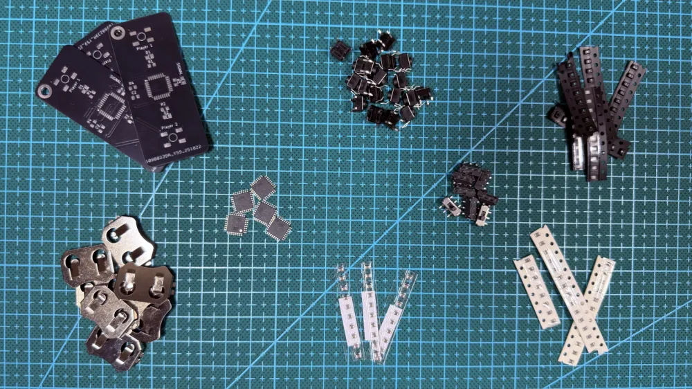
Components for version 1.0:
ATmega328P — 1 pc.
Push buttons 6×6 mm — 2 pcs.
0805 LEDs — 3 pcs.
330 Ohm resistors (for limiting LED current) — 3 pcs.
10 kOhm resistor (pull-up for buttons or reset) — 1 pc.
1 µF capacitor (for power filtering) — 1 pc.
CR2032 battery holder — 1 pc.
Mini power switch — 1 pc. (optional, for convenience).
The cost of the kit is about 350–450 rubles. For version 2.0, additional LEDs (3 per player) and resistors (a total of 7 pcs. 330 Ohm) are added.
The circuit uses minimal external components: no voltage regulators, no external reset (internal pull-up is used). Buttons are connected with debounce in the code.
Step 1: Firmware Development and Programming
The firmware is written in Arduino IDE in C++ (only basic functions are used, without libraries). This allowed for rapid prototyping of the logic, and then compiling it into a clean HEX for the "bare" AVR.
Key features of the code:
Randomized delay:
random(1000, 5000)with a seed from an analog pin.Button debounce: a simple delay of 20 ms.
Anti-cheat: a counter for false presses.
Energy saving: use of
sleep_mode()in the future (not fully implemented in v1.0).Fuse bits: Low = 0xE2 (internal 8 MHz, no divider).
Full code for v1.0 (from GitHub: /src/v1/reaction_game_v1.ino):
// reaction_game_v1.ino

#define LED_CENTER 13  // Central LED (PB5)
#define LED_P1 12      // LED Player 1 (PB4)
#define LED_P2 11      // LED Player 2 (PB3)
#define BTN_P1 2       // Button Player 1 (PD2)
#define BTN_P2 3       // Button Player 2 (PD3)

int scoreP1 = 0;
int scoreP2 = 0;
int falsePressP1 = 0;
int falsePressP2 = 0;
bool blockedP1 = false;
bool blockedP2 = false;

void setup() {
  pinMode(LED_CENTER, OUTPUT);
  pinMode(LED_P1, OUTPUT);
  pinMode(LED_P2, OUTPUT);
  pinMode(BTN_P1, INPUT_PULLUP);
  pinMode(BTN_P2, INPUT_PULLUP);

  randomSeed(analogRead(0));  // Seed for random
}

void loop() {
  resetRound();  // Reset round

  // Readiness signal: 3 blinks
  for (int i = 0; i < 3; i++) {
    digitalWrite(LED_CENTER, HIGH);
    delay(200);
    digitalWrite(LED_CENTER, LOW);
    delay(200);
  }

  // Random delay
  delay(random(1000, 5000));

  // Start: light up center
  digitalWrite(LED_CENTER, HIGH);
  unsigned long startTime = millis();

  while (millis() - startTime < 5000) {  // 5 sec for reaction
    checkFalsePresses();  // Check anti-cheat

    if (!blockedP1 && digitalRead(BTN_P1) == LOW) {
      scoreP1++;
      digitalWrite(LED_P1, HIGH);
      delay(1000);
      digitalWrite(LED_P1, LOW);
      checkWin();
      break;
    }

    if (!blockedP2 && digitalRead(BTN_P2) == LOW) {
      scoreP2++;
      digitalWrite(LED_P2, HIGH);
      delay(1000);
      digitalWrite(LED_P2, LOW);
      checkWin();
      break;
    }

    delay(20);  // Debounce
  }

  digitalWrite(LED_CENTER, LOW);
}

void resetRound() {
  falsePressP1 = 0;
  falsePressP2 = 0;
  blockedP1 = false;
  blockedP2 = false;
}

void checkFalsePresses() {
  if (digitalRead(BTN_P1) == LOW) {
    falsePressP1++;
    if (falsePressP1 > 2) blockedP1 = true;
    delay(20);
  }

  if (digitalRead(BTN_P2) == LOW) {
    falsePressP2++;
    if (falsePressP2 > 2) blockedP2 = true;
    delay(20);
  }
}

void checkWin() {
  if (scoreP1 >= 3) {
    for (int i = 0; i < 5; i++) {
      digitalWrite(LED_P1, HIGH);
      delay(100);
      digitalWrite(LED_P1, LOW);
      delay(100);
    }
    scoreP1 = 0;
    scoreP2 = 0;
  } else if (scoreP2 >= 3) {
    for (int i = 0; i < 5; i++) {
      digitalWrite(LED_P2, HIGH);
      delay(100);
      digitalWrite(LED_P2, LOW);
      delay(100);
    }
    scoreP1 = 0;
    scoreP2 = 0;
  }
}
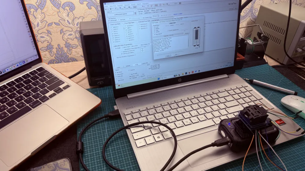
Flashing process:
Compile in Arduino IDE → get .hex.
Use programmer T48.
Write HEX and fuse bits.
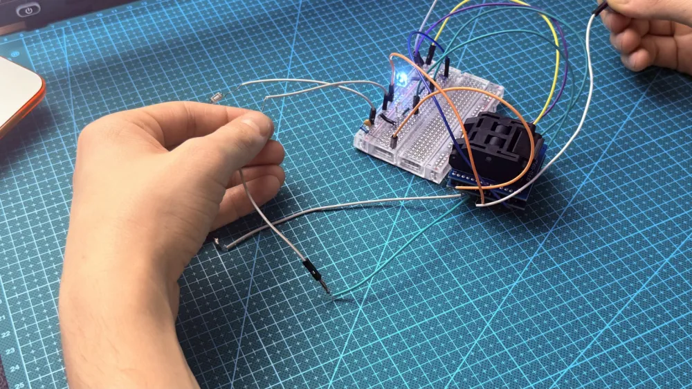
Step 2: Prototyping on a breadboard
With the flashed chip, I assembled the circuit on a breadboard: ATmega in a panel, buttons and LEDs connected to the pins, powered by CR2032 or lab power supply (3 V).
Tested:
Stability at 3 V (idle current ~1 mA).
Randomization (without repeating patterns).
Anti-cheat and debounce (to avoid false triggers).
After debugging — moving to PCB.
Step 3: Designing the board in KiCad
First experience in full design in KiCad. Steps:
Eeschema: I drew a schematic (simple: MCU + LED + buttons + passive components).
Pcbnew: Routing (2 layers, minimum gaps of 0.25 mm). I considered compactness.
3D-viewer: Visualization for verification (see the render on GitHub: images/v1/3D Model.png).
Generation of Gerber files.
Schematic (from GitHub: images/v1/Schematic.png):
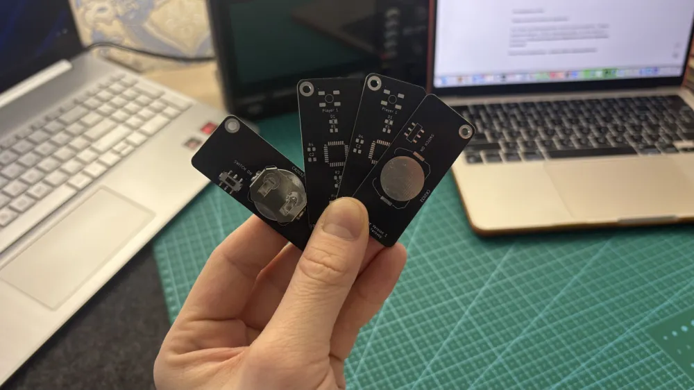
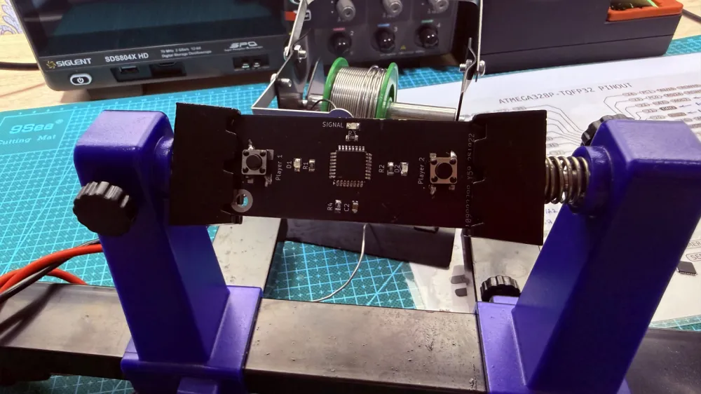
Step 4: Ordering boards and assembly
I uploaded Gerber files to PCBWay: 2 layers, black mask, HASL, 1.6 mm, 5 pcs. Cost with shipping ~2160 rubles (arrived in 2.5 months).
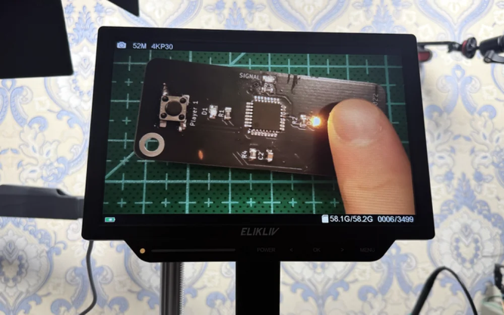
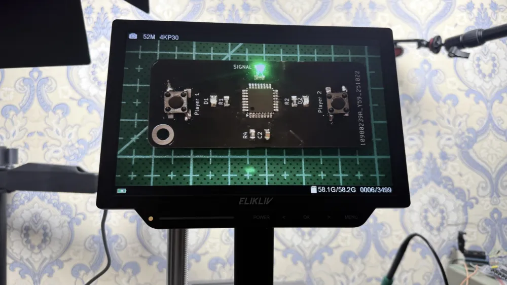
Soldering: Manual, SMD.

The first experience — not perfect, but the board worked almost on the first try.
Results and plans
The project provided experience in the full cycle: from idea to finished device. I learned the nuances of AVR, KiCad, and SMD soldering. Now I feel more confident in embedded systems.
In v2.0: Three LEDs for player scoring, improved silk screening. There is one nuance that I did not fix: the incorrect placement of buttons on the PCB — the footprint turned out to be inverted.
If you found the article useful — like, subscribe or leave a comment. Questions about the code or schematic — in the repository issues. Good luck with your projects! 🚀


Write comment