- DIY
- A
Making Cathode Ray Tubes at Home
This article will discuss relatively primitive CRTs that can be made easily by oneself. In fact, making such tubes is much simpler than most DIY enthusiasts might think.
My motivation for creating them should be obvious. It is definitely not about saving money on building a TV. Rather, it is about the special allure of the process itself. Assembling these tubes closed one of my long-standing Gestalts that arose back in my youth. At that time, I loved to occasionally peek behind the TV to admire the glow of the filaments of its electronic lamps and the magical light of the CRT itself.
I wanted to achieve complete satisfaction from the project. Therefore, I needed to assemble real CRTs capable of directing an electron beam onto a fluorescent screen and at least displaying Lissajous figures by deflecting this beam with magnetic coils. To my great joy, all the CRTs managed to accomplish this task.
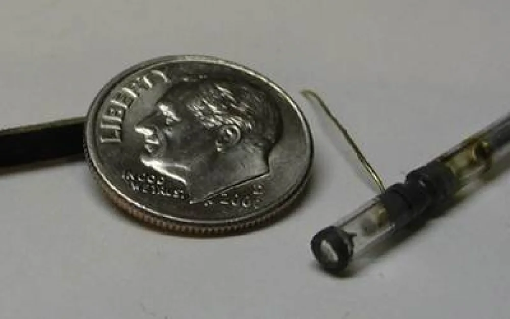
Here are some photos and animations:
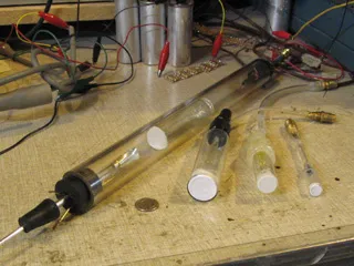
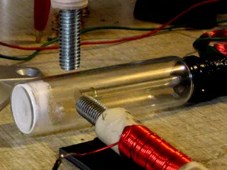
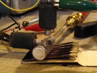
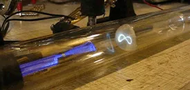
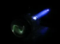
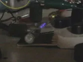
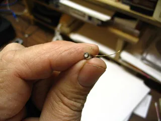
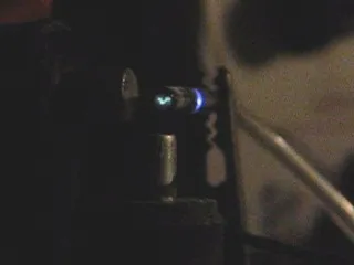
The basis of these CRTs is a cold cathode, meaning simply an electrode without a heater or filament. Essentially, these are modified gas discharge tubes that operate with ionized air in conditions of a readily achievable vacuum level of just a few hundred microns. I'm not sure about the accuracy of the measurements, but I believe my 3-mm CRT operated at a pressure above 1 torr. Generally, the larger the CRT, the lower the vacuum pressure should be. I think the largest specimen, where the bottom of a glass bottle was used as a screen inside a large tube, operated in the range of 100 to 300 microns.
As an improvised high-voltage source, I connected the output of a Variac autotransformer to the primary winding of a neon sign transformer. To rectify the voltage from the secondary winding, I used a high-voltage diode from eBay. I installed three capacitors in series as a filter, connecting a separate shunt resistor of 10 MΩ in parallel to each for even voltage distribution. Alternatively, a high-voltage rectifier can be implemented by connecting several 1N4007 diodes in series, also with 10 MΩ resistors. Without the resistors, the weakest diode in terms of voltage usually fails first, increasing the load on the remaining ones, and eventually all will fail sequentially.
With such a power supply, it is easy to adjust the voltage from zero to 5 kV. The CRTs operated reliably in the range of about 2 to 5 kV.
In each tube, I connected a combined resistor of 1 MΩ in series between the cathode and the negative of the power supply. To ensure a power dissipation of 12.5 W at this resistance, I used 25 resistors of 0.5 W, soldering them in a series-parallel configuration.
In such experiments, there is always a risk of X-ray exposure, so I cannot guarantee their safety. However, as far as I know, the risk only arises at voltages above 15 kV. In all my experiments, I used between 2 and 5 kV.
I have no conditions for creating high-quality vacuum devices, so my CRTs operate with a connected vacuum pump. I regulate the pressure by opening and closing the vacuum line valve. I used a regular mechanical pump, like those used by refrigeration equipment repair technicians, connecting it with standard hoses fitted for 1/4” flare. Professional vacuum technicians would definitely not consider this solution suitable for such work.
I think that with enough desire and persistence, one of these miniature CRTs could be made to work using a simple homemade pump, as described in the Amateur Scientist column of Scientific American magazine from 1966. I plan to try this soon.
Misconception about CRTs and a quote from the work of Morris and Lee
There is a deep misconception that CRTs cannot operate at such high pressures due to the extremely small mean free path of gas molecules. Even many highly educated physicists will tell you that CRTs are incapable of functioning at such pressure levels. However, they often overlook the fact that although the mean free path of air molecules is indeed very short, for electrons, this path is many times longer under the same conditions.
And I want to quote an excerpt from the work of Morris and Lee here. It is taken from a brochure I purchased from them in the late 60s. The brochure describes many interesting experiments with deep vacuum.
“The distance that a molecule or elementary particle can travel directly depends on the distance between free particles around it. For example, air molecules at atmospheric pressure can travel on average several millionths of an inch before deviating due to collisions with other molecules. At a pressure of 1 mm Hg, an air molecule can manage to travel about .002”, while electrons can travel about 3/8”. At a pressure of 1 micron, these distances increase to 2” and 30 feet respectively.”
That is why my CRTs worked perfectly at such a vacuum level that an amateur can easily achieve. Partly, this brochure inspired me to create them.
Imagine a very dense asteroid field, similar to those we see in science fiction movies. In this case, it is easy to notice that the larger the asteroid and the faster it moves, the sooner it will collide with other asteroids. But such scenes always unfold against the backdrop of the impenetrable darkness of deep space. And here it is also easy to imagine that one could fire a tiny and fast bullet that would fly past all these asteroids without hitting any of them. In reality, there are many ways a tiny and fast object can exit an asteroid field in a straight line, avoiding collisions.
Standard Gas Discharge Tube

A standard gas discharge tube is a basic element in the creation of a cold cathode CRT. The diameter of such a tube is about one inch. On the right side is the negative cathode, and on the left side is the positive anode. When a smoothed DC voltage of several kilovolts is applied, pronounced stratifications and characteristic discharge processes occur.
Assembly Process
There are few critical parameters when assembling such CRTs. The distance between the anode of the electron gun and the cathode in my experiments usually ranged from 1” to 2.5”. Meanwhile, the distance between the gun and the screen can vary significantly. The main thing to keep in mind is that the smaller it is, the brighter the final image and the higher the pressure at which the CRT can operate.
Note the photo of all my CRTs: one was assembled from a glass tube with a diameter of 1”. I used the bottom of a glass vial coated with phosphor as the screen, which fit freely into this tube. The resulting screen was positioned opposite the electron gun, and the projected image was best visible from its side. The distance between the screen and the gun could be easily changed by simply tilting the CRT and rolling the vial from side to side.
As an electronic gun, a simple gas discharge tube with an anode, in which I made a small hole, is used. Electrons are attracted to this anode with sufficient speed to pass through the hole, forming an electron beam. If the vacuum cavity extends beyond this hole, we get an electron beam tube. It's that simple! The electrons move through the hole into the vacuum cavity, where they collide with any obstacles in their path, whether it be the wall of the vessel, a phosphor, paper, metal, or anything else. Ultimately, they always return to the positive anode left behind.
This electron beam can easily be deflected using a magnetic field created by a nearby magnet or coil. I managed to achieve this deflection using an electrostatic plate, but there are nuances compared to commercial CRTs, where the plate is in ionized gas. More on this shortly.
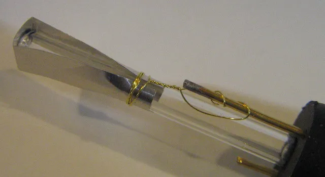
Most of the electron guns I made from ordinary glass tubes with an outer diameter of 5-6 mm. A strip of thick aluminum foil with a small hole (which can be cut from a baking tray) will suffice as a positive anode (in the photo above). By wrapping the foil around the edge of the tube, it needs to be pierced with a pin from the end at the center. Alternatively, a small diameter metal tube can also be used for the anode. I also assembled one gun by simply narrowing one end of the glass tube and placing the anode elsewhere in the CRT.
As a cathode (not visible in the photo), you can take an aluminum welding rod and securely place it in the opposite end of the tube in any convenient way. Keep in mind that to minimize sputtering, it's better to use aluminum. By sputtering, I mean the process where metal atoms fly off the cathode and settle on the inner wall of the tube. This reduces the lifespan of the CRT. Aluminum has a very low sputtering rate compared to other metals like copper or silver.
The electrical contacts protruding from the rubber plug can also be made from a welding rod with a diameter of 1/16” or less. Or you can take a suitable piece of wire. Just secure it in a drill and carefully screw it in.
The entire setup with the rubber stopper (visible in the photo) can be inserted into a thicker (1”) glass tube or vial. The drawing below shows how it all looks. Before inserting the electron gun into the vial, I took some phosphor (from a broken fluorescent lamp), mixed it with water, swirled this mixture at the bottom of the vial, and left it to dry.
Each CRT has an optimal vacuum level at which it operates best. And this is always the maximum level (that is, minimum pressure) that can be achieved before the electron discharge stops. In any discharge tube, it stops when the pressure drops to a sufficiently low level. The smaller the diameter of the tube, the higher the pressure it can operate at. This means that a CRT with a small-diameter electron gun should function at a higher pressure than one with a larger-diameter gun. That is, CRTs with "small-caliber" electron emitters will generally be smaller due to the higher operating pressure and shorter beam path.
There are many materials that will glow when struck by an electron beam. If you darken the room, you can see a blue spot in the area where the beam contacts the walls of the glass vessel.
As I mentioned, for coating the screens of most of my CRTs, I used phosphor that I collected from a lamp that broke when it fell to the floor several years ago. I cursed quite a bit at that time, but then I realized that I had the opportunity to collect material that I had wanted to experiment with for a long time. Phosphor is a fine white powder that can easily be scraped from the shards of a fluorescent lamp. And for assembling the CRT, you need very little of it. This powder is one of the best candidates for coating the tube screen, as that is its original purpose—to glow when bombarded with electrons. I simply mixed the phosphor with a small amount of water, applied it to the bottom of the CRT, and left it to dry.
Yes, yes, yes!!! I am well aware of the poisoning threat from contact with the contents of fluorescent lamps, but I believe that these threats are not as serious as those we face in everyday life. However, keep in mind that when extracting the phosphor from the lamps, you do so at your own risk. I have my own opinion, but I am definitely not an expert to give advice regarding the associated threats. I will only say that since my youth I have heard many warnings about the special danger of cuts from shards of fluorescent lamps.
I also found out that in low light, a piece of paper colored with a marker can serve as a screen. This can be an impressive trick if you want to impress your girlfriend. Such a screen, as you might guess, is best viewed when looking at it from the side of the electron gun. However, soon the area that was hit by the electrons the most began to burn out. It might be worth trying a flat piece of ceramic as a screen, also colored with a marker. Such a screen should work well for viewing from the back. The only problem is that I don't have suitable ceramic, so I couldn't test it.
Also, under the electron beam, Clorox bleach powder will glow. I haven’t tried it either, but if this powder is ground well and turned into a paste by adding a little water, it could make a usable screen phosphor. However, the marker and bleach powder clearly glow worse under the electron beam than under UV light.
Illustrations
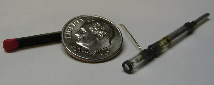
The drawings below show the schematic of a typical CRT using a regular glass vial. The size of such a tube can be almost any. In the second image, there is a tiny CRT with an outer diameter of 3 mm.
In this miniature CRT, the distance from the anode to the screen and from the cathode to the anode is approximately 1/8” — 3/16”.
To make its screen, I heated a glass tube until it melted and pulled it into a thin thread. After breaking this thread in half, I placed it back in the flame to form a small sphere. I removed the resulting sphere from the fire and pressed it between two microscope slides, leaving it that way until it cooled. I had to repeat this process about four times to avoid breaking the fragile part when breaking off the remaining thread. After that, I glued the finished plate to the end of the tube with epoxy glue.
Before gluing the anode, I poured a little phosphor into the tube and shook it so that it settled on the screen.
The electron gun was made from a piece of brass tubing 3/8” long and 1/16” in diameter. To narrow the end directed at the screen, I held the tube in a drill chuck and lightly "sharpened" it against a steel plate.
Launching the CRT
I will describe the principle of operation of such CRTs. High voltage is applied to the anode, and a vacuum pump is started simultaneously. Almost immediately, the electron gun begins to glow. As the pressure drops, characteristic glowing strata occur in it. The lower the pressure, the wider the strata and the closer they shift towards the anode, gradually disappearing. When there are almost no strata left, a faint glow begins to appear on the screen. This means that the pressure has become low enough for some of the electrons passing through the anode to reach the screen. As the pressure continues to decrease, the spot on the screen becomes clearer and brighter. At this moment, the CRT operates at an optimal vacuum level (pressure). I always try to keep the system in this state by opening/closing the pump line valve. With further pressure reduction, the discharge glow in the electron gun completely fades, and with it, the screen also fades. Closing the valve allows the pressure to rise, followed by the return of the glow.
It is easy to see how the light coming from the discharge tube hits the screen, forming an electronic spot. You can confirm its reality if you bring a magnet close to the CRT, which will allow you to easily move the spot from side to side.
To deflect the beam electronically, coils need to be placed next to the tube. For controlling the centering, again a magnet positioned at the right distance from the CRT will work.
Electrostatic Deflection
Despite the fact that these simple CRTs are well-suited for magnetic deflection, I managed to implement vertical deflection using an electrostatic plate. I didn’t put much effort into it, so you might get different results.
Electrostatic plate for vertical deflection and magnetic coil for horizontal
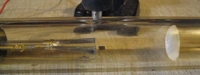
In all my experiments with CRTs, I connected the anode to ground and applied a negative DC voltage of several kilovolts to the cathode through a 1 MΩ resistor. All voltage measurements applied to the deflecting plate were set relative to ground (positive anode).
To control the plate, I used sound from an analog synthesizer, connecting the output of the audio amplifier to a step-up transformer. I added a negative offset voltage of 200 - 300 V in series to the transformer output so that the audio signal could deflect the beam both positively and negatively. Using a horizontally deflecting magnetic coil controlled by a 60 Hz signal allowed me to visualize sound just as it is visualized when using an oscilloscope. A short video with snippets of my experiment is available on YouTube.
In ionized gas, the deflecting plate works somewhat differently than in the ultra-high vacuum used in commercial CRTs. In this case, the gas acts as a conductive screen, preventing the influence of the plate or grid’s field. I found this out during experiments with homemade electron tubes. When the residual gas inside was ionized, the grid ceased to affect the electron beam between the cathode and anode.
In commercial CRTs, the deflecting plate repels the electron beam when a negative voltage is applied and attracts it when a positive voltage is applied.
In the case of CRT with a cold cathode, I observed that when a negative voltage was applied to the plate, the beam deflected as expected. However, when a positive voltage was applied, there was no deflection. Instead, the beam became more focused. Moreover, the plate did not need to be near the electron beam — it could be located anywhere in the CRT.
When a positive voltage was applied to the deflection plate, a weak current arose between it and the anode.
At first glance, the photo above may seem unusual. It looks like they are opposing each other. But this is quite natural, as the plate deflects the beam in the direction of the field, while the magnetic coil does so at a right angle.
I was unable to achieve both horizontal and vertical deflection using plates. Therefore, here I used a coil for horizontal deflection. I read somewhere that Braun — the inventor of the CRT — came to similar results when he tried to apply electrostatic deflection to his cold cathode CRT.

Write comment