- Hardware
- A
Creating a Gigabit Switch on Linux
Network switches are simple devices: receive a packet, send a packet. Fortunately, people figured out how to complicate them and invented managed switches.
They are usually implemented by adding a web interface that configures settings and controls parameters such as port status. More expensive switches have access to alternative interfaces, such as Telnet and serial console ports.
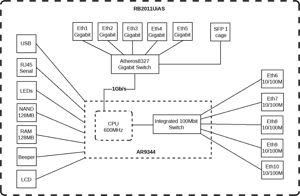
However, there is a second category of managed switches that are not immediately remembered - these are switches that are inside consumer-grade routers. These routers are small Linux devices that have a switch chip inside, one or more ports internally connected to the CPU, and the rest are exposed as physical ports.
Here is an example of a device where this is documented. I always thought that the configuration of these switch-connected ports was a convenient abstraction of the web interface, but I was surprised to learn that thanks to DSA and the switchdev subsystem in Linux, these ports turn out to be fully functional "local" network ports. Unfortunately, because these are practically the only ports available inside integrated routers, they are quite difficult to experiment with.
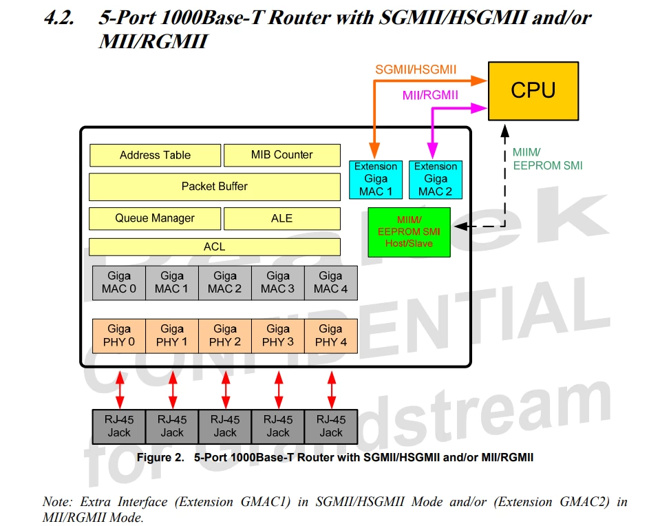
What is shown in the diagram as a single line is actually the connection of the router's SoC and the switch via the SGMII bus (or possibly RGMII in this case) and the control bus, SMI or MDIO. Network switches have many such funny abbreviations that even when fully deciphered seem incomprehensible if you don't know what is what.
It is simply impossible to control a standard commercial switch using this system because the required connections of the switch chip are not disclosed for this. There is only one option left...
Creating your own gigabit network switch
Surely, creating your own network communicator can't be particularly difficult? These devices are sold for the price of a cup of coffee, and given the cost, they must have a high degree of integration. I don't see many homemade switches on the Internet, so it can be assumed that the chips for them are quite difficult to find...
But no, they are very easy to get. They even have a datasheet. So I created a new KiCad project and got to work.
I'm glad that there is at least some datasheet for this chip, because for Realtek devices they are usually not available, but it is still quite modest. I decided to limit myself to searching for devices that have available schematics for similar Realtek chips to understand how to integrate them, and studied a lot of documentation on how to implement Ethernet in a device in general.
The implementation of the chip initially seemed very complicated: it requires about seven separate power circuits and has many very poorly documented communication interfaces. After studying other implementations, I concluded that the easiest way to power it is to connect all networks with close voltage intervals together, and we will only need a 3.3V and 1.1V regulator.
It seems that additional communication buses are required for additional ports, which I don't seem to need. As a switch chip, I chose the RTL8367S. This is a very widely used five-port gigabit chip, although it is not actually five-port. It is a seven-port switch chip, where five ports have an integrated PHY, and two are intended for connections to the CPU.
However, my plan was different: although all these CPU ports are available, in fact, in the Linux switchdev subsystem, nothing requires the CPU to be connected to these ports. Instead, I will connect to port 0 of the switch with a network cable, and as far as the switchdev driver is concerned, there is no Ethernet PHY in between.
The next problem was the configuration of the switch chip: there are many configuration systems, and the datasheet does not specify which system is minimally required for the device to work as a regular "dumb" switch. I will briefly describe the chip configuration options:
There are eight pins on the chip that are read at startup. These pins are shared with the LED port pins, making the design process quite inconvenient. Additionally, switching from boost to buck requires connecting the LED in a different orientation.
There is an I2C bus that can be connected to an EEPROM chip. The pins for it are shared with the SMI bus, which I need for the chip to communicate with Linux. There is a pin configuration that allows selecting one of two EEPROM size ranges, but it is not specified anywhere what this setting changes.
There is an SPI bus that supports connecting a NOR flash chip. It can store either configuration registers or firmware for the built-in 8051 core; this depends on the configuration of the pins read at startup. The SPI bus pins are also shared with one of the CPU's network ports.
There is also an available serial port, but from what I have studied, it probably does nothing unless firmware is loaded into the 8051.
To figure it out, I simply ordered a board and soldered the connections differently until everything worked. I added a pad for the flash chip, which turned out to be unnecessary, and implemented jumpers for all the configuration pins. I discarded all the LEDs because making them configurable would have been quite difficult.
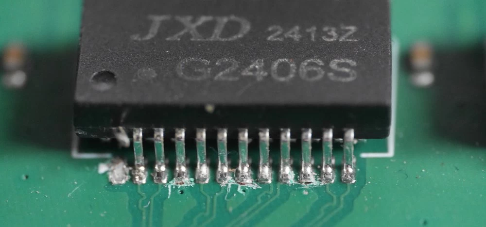
Next, I began to figure out how to properly implement Ethernet. There is a lot of documentation written about this, which gives the impression that gigabit Ethernet requires precision engineering, impedance-controlled boards, and the blessing of the Ethernet gods themselves. This does not quite align with reality, as these switches are very cheap to manufacture and seem to work quite well. So I decided to open up a switch to check if all these decoupling capacitors and impedance matching boards are used in real devices. As it turned out, all this is not particularly important.
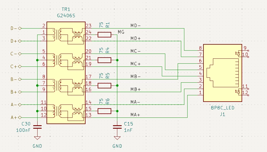
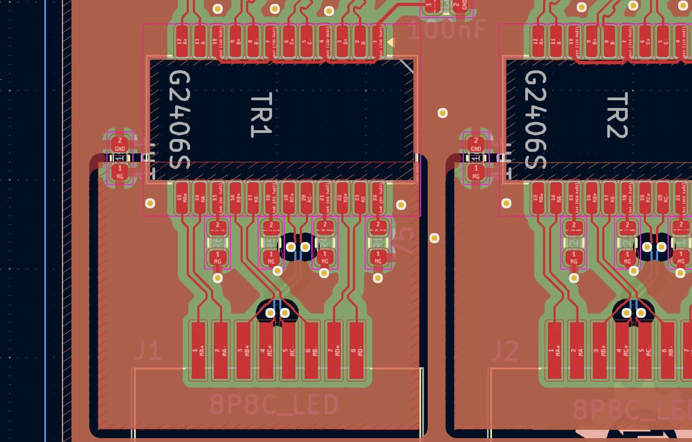
This is the scheme I ended up with, but it differs from my test PCB. However, I did almost everything right the first time.
It seems that it is important here to match the asymmetry of the pairs, but matching the length of the four network pairs is completely useless; this is mainly due to the fact that network cables do not have the same twisting frequency for the four pairs, so their length varies greatly within the cable.
The pairs between the transformer and the RJ45 connector have their own ground plane, connected to the main ground through a capacitor. The pairs after the transformer are simply on the main board ground.
In the first version of the board, I made a mistake by forgetting the capacitor that connects the branches from the central point of the transformer on the side of the switch to the ground. Because of this, Ethernet practically did not work, so I had to manually cut tiny tracks on the board to disconnect from the ground. In my test system, there is no capacitor at all, and all central points are isolated from the ground. It seems that in such a scheme everything works, but in the final version, this capacitor is added.
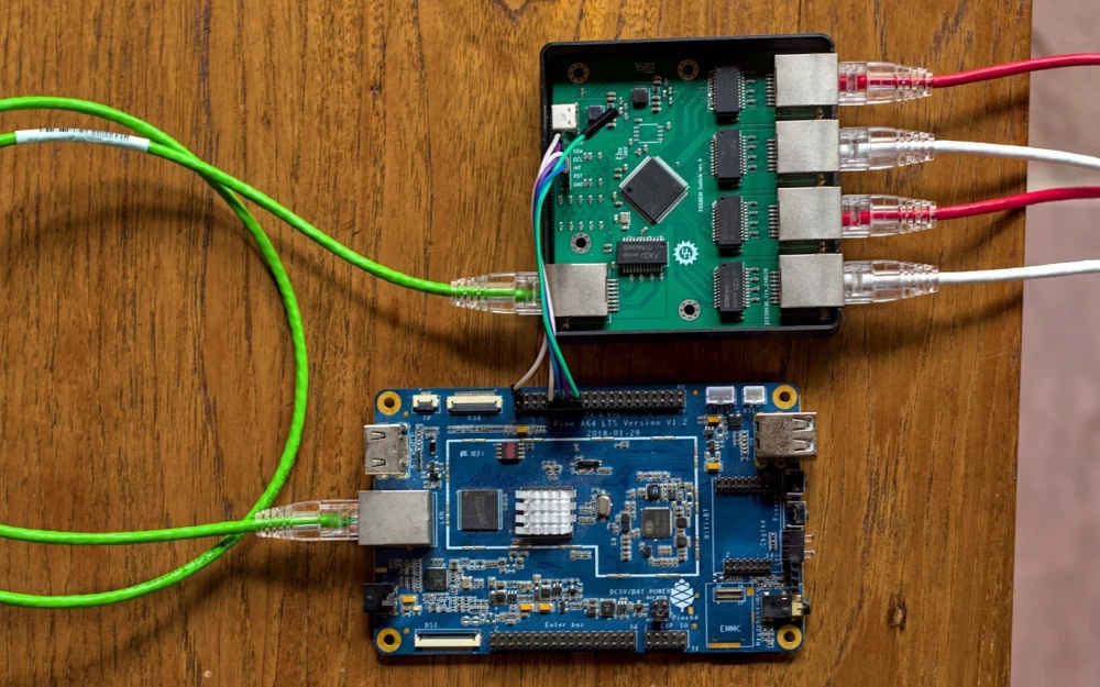
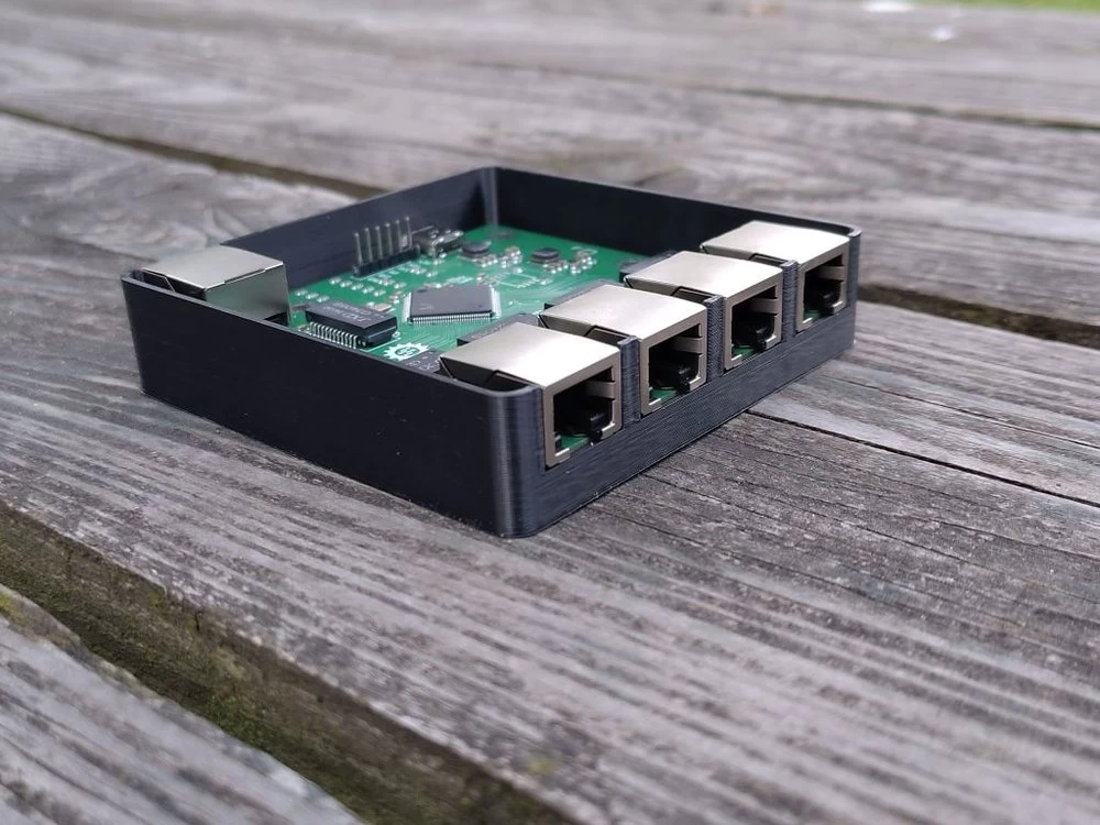
As a result, a rather strange gigabit switch turned out. Four of its ports are output in one direction, one looks in the opposite direction, and the device is powered through a 2.54 mm pin connector. In addition, I added a pad for a USB Type-C connector to conveniently supply power without the need to use DuPont cables.
Connecting the system to Linux
For my test system, I chose the PINE64 A64-lts board because its connectors are approximately in the places I need. It is also important that this is not x86, because configuring requires changing the device tree, and it is impossible to do this on a platform where there are no device trees.
The first thing I had to do was rebuild the kernel for the board, because in most kernels these kernel modules are simply disabled. To do this, I enabled the following options:
CONFIG_NET_DSAfor the Distributed Switch Architecture systemCONFIG_NET_DSA_TAG_RTL8_4for port tagging of this Realtek switch chipCONFIG_NET_SWITCHDEV— driver system for network switchesCONFIG_NET_DSA_REALTEK,CONFIG_NET_DSA_REALTEK_SMI,CONFIG_NET_DSA_REALTEK_RTL8365MBfor the switch chip driver itself
It was more difficult to figure out how to make all this load. Theoretically, you can create a device tree overlay for this to be loaded using U-Boot. I decided not to do this and instead patch the device tree for the A64-lts board, because I am rebuilding the kernel anyway. As a result, I came to the following device tree change:
diff --git a/arch/arm64/boot/dts/allwinner/sun50i-a64-pine64-lts.dts b/arch/arm64/boot/dts/allwinner/sun50i-a64-pine64-lts.dts
index 596a25907..10c1a5187 100644
--- a/arch/arm64/boot/dts/allwinner/sun50i-a64-pine64-lts.dts
+++ b/arch/arm64/boot/dts/allwinner/sun50i-a64-pine64-lts.dts
@@ -18,8 +18,78 @@ led {
 gpios = <&r_pio 0 7 GPIO_ACTIVE_LOW>; /* PL7 */
 };
 };
+
+switch {
+compatible = "realtek,rtl8365rb";
+mdc-gpios = <&pio 2 5 GPIO_ACTIVE_HIGH>; // PC5
+mdio-gpios = <&pio 2 7 GPIO_ACTIVE_HIGH>; // PC7
+reset-gpios = <&pio 8 5 GPIO_ACTIVE_LOW>; // PH5
+realtek,disable-leds;
+
+mdio {
+compatible = "realtek,smi-mdio";
+#address-cells = <1>;
+#size-cells = <0>;
+
+ethphy0: ethernet-phy@0 {
+reg = <0>;
+};
+
+ethphy1: ethernet-phy@1 {
+reg = <1>;
+};
+
+ethphy2: ethernet-phy@2 {
+reg = <2>;
+};
+
+ethphy3: ethernet-phy@3 {
+reg = <3>;
+};
+
+ethphy4: ethernet-phy@4 {
+reg = <4>;
+};
+};
+
+ports {
+#address-cells = <1>;
+#size-cells = <0>;
+
+port@0 {
+reg = <0>;
+label = "cpu";
+ethernet = <&emac>;
+};
+
+port@1 {
+reg = <1>;
+label = "lan1";
+phy-handle = <ðphy1>;
+};
+
+port@2 {
+reg = <2>;
+label = "lan2";
+phy-handle = <ðphy2>;
+};
+
+port@3 {
+reg = <3>;
+label = "lan3";
+phy-handle = <ðphy3>;
+};
+
+port@4 {
+reg = <4>;
+label = "lan4";
+phy-handle = <ðphy4>;
+};
+};
+};
 };
It loads the driver for the switch with realtek,rtl8365rb, this driver supports a wide range of Realtek switch chips, including the RTL8367S, which I used in my device. I removed the CPU ports from the example in the documentation and simply added definitions for five regular switch ports.
The important part is in port@0 — this is the port located at the back of my switch and connected to the A64-lts; I tied it to &emac, which is a reference to the computer's Ethernet port. The other ports are tied to the corresponding PHYs in the switch chip.
At the beginning of the code, three GPIOs are also defined, they are tied to SDA/SCL and Reset on the switch board to make communications work. After starting the system, we get the following:
1: lo:  mtu 65536 qdisc noop state DOWN qlen 1000
    link/loopback 00:00:00:00:00:00 brd 00:00:00:00:00:00
2: eth0:  mtu 1508 qdisc noop state DOWN qlen 1000
    link/ether 02:ba:6f:0c:21:c4 brd ff:ff:ff:ff:ff:ff
3 lan1@eth0:  mtu 1500 qdisc noop state DOWN qlen 1000
    link/ether 02:ba:6f:0c:21:c4 brd ff:ff:ff:ff:ff:ff
4 lan2@eth0:  mtu 1500 qdisc noop state DOWN qlen 1000
    link/ether 02:ba:6f:0c:21:c4 brd ff:ff:ff:ff:ff:ff
5 lan3@eth0:  mtu 1500 qdisc noop state DOWN qlen 1000
    link/ether 02:ba:6f:0c:21:c4 brd ff:ff:ff:ff:ff:ff
6 lan4@eth0:  mtu 1500 qdisc noop state DOWN qlen 1000
    link/ether 02:ba:6f:0c:21:c4 brd ff:ff:ff:ff:ff:ff
There is a regular eth0 device and four interfaces for the switch ports defined in the device tree. To make them do something, the interfaces usually need to be turned on first:
$ ip link set eth0 up
$ ip link set lan1 up
$ ip link set lan2 up
$ ip link set lan3 up
$ ip link set lan4 up
$ ip link
1: lo:  mtu 65536 qdisc noop state DOWN qlen 1000
    link/loopback 00:00:00:00:00:00 brd 00:00:00:00:00:00
2: eth0:  mtu 1508 qdisc mq state UP qlen 1000
    link/ether 02:ba:6f:0c:21:c4 brd ff:ff:ff:ff:ff:ff
3: lan1@eth0:  mtu 1500 qdisc noqueue state LOWERLAYERDOWN qlen 1000
    link/ether 02:ba:6f:0c:21:c4 brd ff:ff:ff:ff:ff:ff
4: lan2@eth0:  mtu 1500 qdisc noqueue state LOWERLAYERDOWN qlen 1000
    link/ether 02:ba:6f:0c:21:c4 brd ff:ff:ff:ff:ff:ff
5: lan3@eth0:  mtu 1500 qdisc noqueue state UP qlen 1000
    link/ether 02:ba:6f:0c:21:c4 brd ff:ff:ff:ff:ff:ff
6: lan4@eth0:  mtu 1500 qdisc noqueue state LOWERLAYERDOWN qlen 1000
    link/ether 02:ba:6f:0c:21:c4 brd ff:ff:ff:ff:ff:ff
Now the switch is on and, as you can see, a cable is connected to the third port. This system borrows a lot from the Linux network system, so it "just works"(TM). Here are a couple of examples:
If you add multiple LAN ports to a standard Linux bridge, the switchdev system will create a joint bridge of these ports in the switch chip so that Linux does not have to forward this traffic.
Things like
ethtool lan3simply get link information. Andethtool -S lan3returns all standard status information, including packets that are fully processed by the switch.
Limitations
There are some aspects that reduce the convenience of working with such a system. Firstly, it is the need to create your own network switch or open a ready-made one to find suitable connections.
This system cannot be used on regular computers/servers because device trees are needed to configure the kernel, and most computers do not have kernel-controlled GPIO contacts to connect the switch.
As far as I understand, there is still no way to use this system with a network port on the computer side if it is not fixed; network USB interfaces do not have a device tree node descriptor that could be used to specify the connection port.
There is a possibility that some of these limitations can be circumvented: there may be some strange USB device that opens the GPIO subsystem contacts; maybe you can somehow load switchdev not on an ARM device, but for this you need to study the documentation...




Write comment