- Hardware
- A
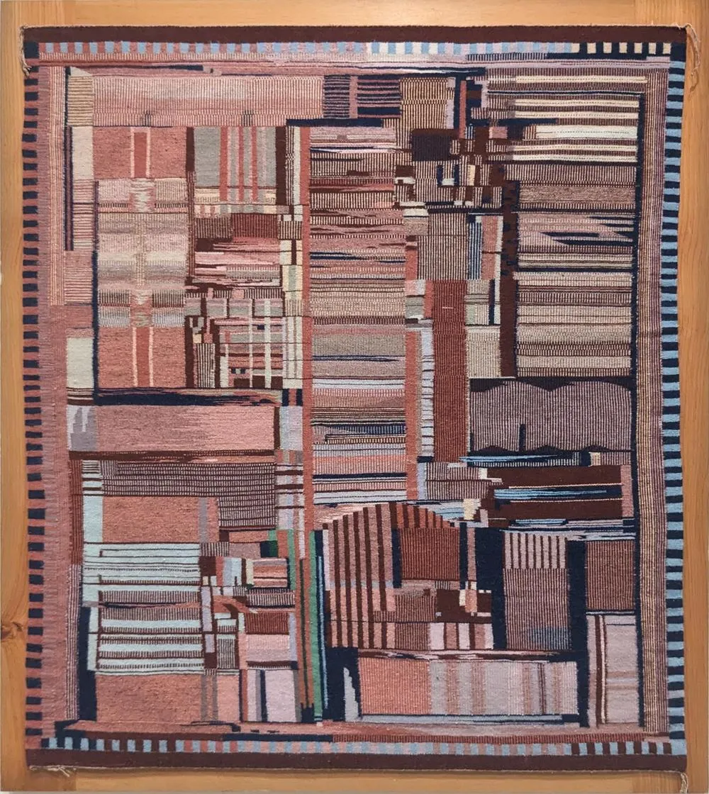
Navajo Rug in the Shape of an Integrated Circuit: Timer 555
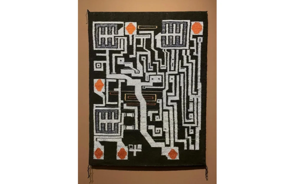
Renowned weaver Merilu Schultz from the Navajo tribe recently completed a complex rug featuring thick white lines on a black background, interspersed with reddish-orange diamonds. While this creation may seem abstract, it represents the internal schematic of a tiny silicon chip, the Timer 555. This chip has hundreds of applications, from sound generators to automotive windshield wiper controllers. Once, the 555 was the best-selling integrated circuit in the world, counting billions of devices. But how did a chip turn into a rug?
The 555 chip consists of a tiny piece of silicon with a layer of metal conductors on top. On the rug, these conductors are represented by thick white lines, while the silicon forms the black background. Reddish-orange diamonds are located around the perimeter of the rug, corresponding to the connections between the chip and the eight contacts. These connections are made by tiny gold wires attached to square pads on the chip. The schematic of the 555 chip contains 25 transistors (silicon devices capable of turning on and off). In the rug's design, three large transistors are highlighted (colored squares with the pattern 王 inside), while the other transistors are represented by small dots.
The inspiration for creating the rug came from a photograph of the 555 timer crystal taken by Antoine Berkovich (Siliconinsider); I suggested this photo to Merilu Schultz as a possible theme for the rug. The diagram below shows a comparison of the rug (on the left) with the photograph of the crystal (on the right). As can be seen, the weaving is very close to the actual chip, but there are slight artistic differences. For instance, two contact pads and the serial number were removed, and the circuits at the top were simplified.
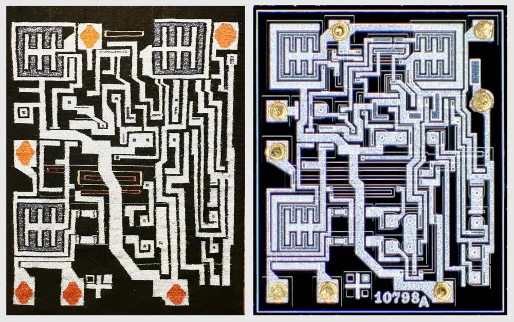
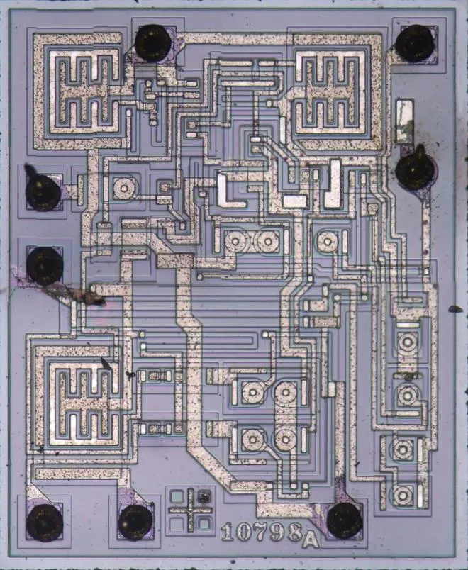
Antoine took a photo using a dark field microscope — a special type of microscope that creates images on a black background. In this image, the metallic layer on top of the crystal is highlighted. For comparison, an image created by a standard light field microscope is shown below. During the production of the chip, areas of silicon are doped with impurities to create transistors and resistors. These areas are visible in the image below as small color variations in the silicon.
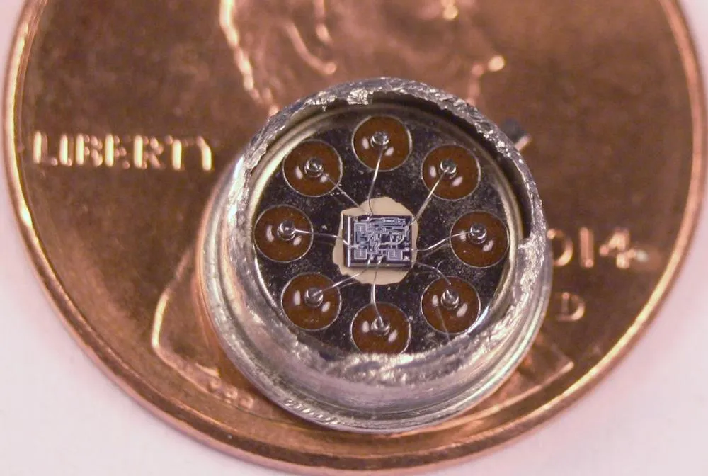
In the weaving of the carpet, the design of the chip looks almost monumental, making it easy to forget that the chip itself has microscopic dimensions. I purchased a version of the chip in a round metal case instead of the traditional rectangular black plastic. By cutting off the top of the metal case, you can see inside a tiny chip with eight gold connectors linking the crystal to the legs of the case. If you look closely, you can notice three large transistors.
The artist Merilu Schultz has been weaving chip carpets since 1994, when Intel commissioned her to create a carpet inspired by the Pentium processor as a gift for the American Indian Science & Engineering Society (AISES). Although Schultz studied weaving since childhood, the Pentium carpet became a challenging task for her due to the complex pattern and lack of symmetry; in one day's work, the size of the carpet could increase by only an inch. This stunning carpet was made from the wool of Navajo-Churro longhorn sheep and dyed with traditional plant dyes.
In preparation for making the 555 chip carpet, Schultz experimented with various materials. Silver and gold metallic threads symbolize the aluminum and copper of the chip. The artist explained that "weaving the metal threads took much more time," but it was worth the effort because "when a ray of light falls on the metal in the dark, it looks magnificent." The black and lavender colors were achieved using aniline dyes. The beautiful purple color comes from the natural dye of campeche wood, but it fades over time, so Schultz chose an aniline dye instead. The lavender shades are dedicated to the weaver's mother, who left us in February: purple was her favorite color.
Inside the chip
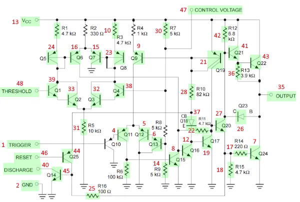
How does the 555 chip generate specific time delays? To select the timing, external components need to be added—resistors and a capacitor. The capacitor charges at a rate controlled by the resistor. When the capacitor is fully charged, the 555 chip switches modes and begins to discharge the capacitor. This is similar to filling a sink with water: if we have a large sink (capacitor) and a thin stream of water (a big resistor), the sink fills slowly. But if the sink (capacitor) is small and there is a lot of water (a small resistor), then the sink fills quickly. Thanks to the use of different resistors and capacitors, the 555 timer can generate time intervals ranging from microseconds to hours.
Below I have shown which parts of the carpet correspond to the electronic components of the physical chip.
Hidden text
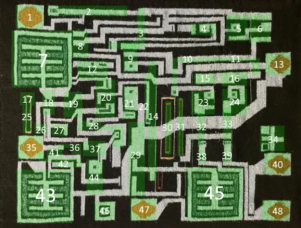
1. Contact pad. When the voltage at the Trigger contact drops to 1/3 Vcc, the trigger is set.
2. Contact pad. Ground contact. This pad is not present on the board.
3. Resistor R6 is a load for the output of the trigger comparator. This resistor is not present on the board.
4. Transistors Q10 and Q11 form a Darlington pair, making up half of the differential pair of the trigger comparator.
5 and 6. Transistors Q12 and Q13 form a Darlington pair, making up half of the differential pair of the trigger comparator.
7. Transistor Q24 is a high-current transistor designed to pull the output low.
8. Transistor Q15 resets the trigger based on the output signal of the trigger comparator.
9. Transistor Q9 together with Q19 forms a current mirror providing current for the trigger comparator.
10 and 11. Resistors R1, R2, and R3 are emitter resistors in the current mirrors. Since the resistance of R2 is significantly lower, the output currents are amplified. These resistors are not present on the board.
12 and 19. Transistors Q16 and Q17 are connected, forming the trigger.
13. Contact pad. Vcc is the power contact.
14 and 30. Resistors R7, R8, and R9 form a voltage divider that sets the reference voltages for the comparators. These resistors are not present on the board.
15 and 23. Transistors Q7 and Q8 form a somewhat unconventional current mirror. When activated, it locks Q6, causing the comparator to turn off more sharply.
16 and 24. Transistors Q5 and Q6 form a current mirror that amplifies the output of the comparator.
17 and 25. Resistors R14 and R16 split the output signal from transistor Q20.
18. Resistor R15 biases the output transistor Q24 to a low level to keep it in the off state. This resistor is not present on the board.
20. This area contains only connections.
21. Transistor Q19 forms a current mirror. It consists of two transistors with combined emitters and bases.
22. Resistor R11 serves as feedback for the trigger. This resistor is not present on the board.
26. Transistor Q23 is connected in diode configuration to control transistor Q21.
27. Transistor Q20 acts as a buffer for the trigger output and controls the output transistors.
28. Resistor R10 sets the current through the current mirror Q19. This resistor is not present on the board.
29. This area contains only connections.
31. Resistor R5 controls the current through the threshold comparator.
32 and 38. Transistors Q3 and Q4 form a Darlington pair, making up half of the differential pair of the threshold comparator.
33 and 39. Transistors Q1 and Q2 form a Darlington pair, making up half of the differential pair of the threshold comparator.
34. Alignment marks are used in the manufacturing process to ensure layer alignment of the chip.
35. Contact pad. The Output contact provides the output signal of the 555 timer.
36. Resistor R13 sets the bias for the output transistor Q22. This resistor is not present on the board.
37. Transistor Q18 is connected in diode configuration to boost the reset signal level.
40. Contact pad. The timing capacitor can be discharged through the Discharge contact.
41. Transistor Q21 controls the output transistor Q22.
42. Resistor R12 biases the output transistor Q21 to a high level. This resistor is not present on the board.
43. Transistor Q22 is a high-current transistor designed to pull the output high.
44. Transistor Q25 buffers the signal from the Reset contact and resets the trigger.
45. Transistor Q14 is a high-current transistor that controls the Discharge contact.
46. Contact pad. The Reset contact is used to reset the trigger. There are no connections for this pad on the board.
47. Contact pad. The Control Voltage contact allows for voltage changes of the comparators.
48. Contact pad. When the voltage at the Threshold input contact reaches 2/3 Vcc, the trigger resets, and the timing capacitor discharges.
For example, two large square transistors turn on and off the chip output, while a third large transistor discharges the capacitor when it is fully charged. (More precisely, the charge of the capacitor changes between 1/3 and 2/3 of the full charge to avoid issues that arise when approaching the state of being fully "empty" or "full".) The chip has circuits called comparators that determine when the voltage of the capacitor reaches 1/3 or 2/3, switching between discharging and charging at these points. If you are interested in technical details about the 555 chip, read my previous articles: about the early versions of the 555 chip, and about the 555 timer, similar to the one used for weaving, and about a more modern CMOS version of the 555 chip.
Conclusion
The similarities between the weaving art of the Navajo people and the patterns of integrated circuits have been noted for a long time. Marilou Schultz's circuit board rugs have turned these visual metaphors into tangible pieces of art. However, this connection is not just metaphorical; in the 1960s, Fairchild Semiconductor hired many workers from the Navajo tribe for its chip assembly lines in Shiprock, New Mexico. I wrote about this complex history in an article The Pentium as a Navajo Weaving.
This work was exhibited at SITE Santa Fe Once Within a Time. More about Marilou Schultz's art can be found in the article The Diné Weaver Who Turns Microchips Into Art or from an interview with her on YouTube.
I express my deep gratitude to Marilou Schultz for discussing her work with me. I thank First American Art Magazine for providing the photograph of her 555 rug.


![From Virtual Hands to AI for Survivalists: Curious Open Agent OSes [and One Hardware Project]](https://cdn.tekkix.com/imgs/2026/05/habrcom/big/ce0b1057616faed51cd8b9f3b2b9.webp)
Write comment