- Hardware
- A
Homemade ARM laptop, is it real?
I've always wanted to build my own laptop. Now, thanks to advances in ARM-based systems, this has become much easier and entirely feasible.
In this article, I will talk about the possible options for creating your own portable device based on ARM, provide examples of similar devices, describe my own journey and the problems I encountered.
Introduction
Unlike x86 processors, ARM chips contain a number of peripherals onboard, which greatly simplifies the motherboard design. For example, there are even RV1106G3 processors that have RAM built-in right away. To develop the simplest computer based on such a processor, all you need to do is lay out the board—it's no more complicated than making an Arduino board based on a microcontroller. One example of such boards are the Luckfox Pico single-board computers, which I once wrote about in an article.
Also, ARM processors are mostly designed for low power consumption (up to 5 W), which greatly simplifies the power supply and cooling circuit.
Another important advantage of ARM is the popularity of single-board computers based on them. Many manufacturers make their board schematics publicly available, which greatly helps in design.
Motherboard Options
Currently, there are several options for implementing a motherboard for your portable device:
Custom Board with a Processor
The first and most obvious option is to develop your own motherboard with a soldered processor and all the necessary peripherals.
In such a configuration, one of the simplest implementations can be achieved. For example, you could take an RV1106G3 processor, add a microcontroller connected via UART and a simple power circuit, and implement keyboard control and screen output on the microcontroller. That's about it! As a result, you get the simplest portable computer with Linux for console work. No complex circuits or drivers are needed. However, this approach also has many drawbacks. Low performance and a console interface make such a device specific and not particularly interesting for a wide range of tasks.
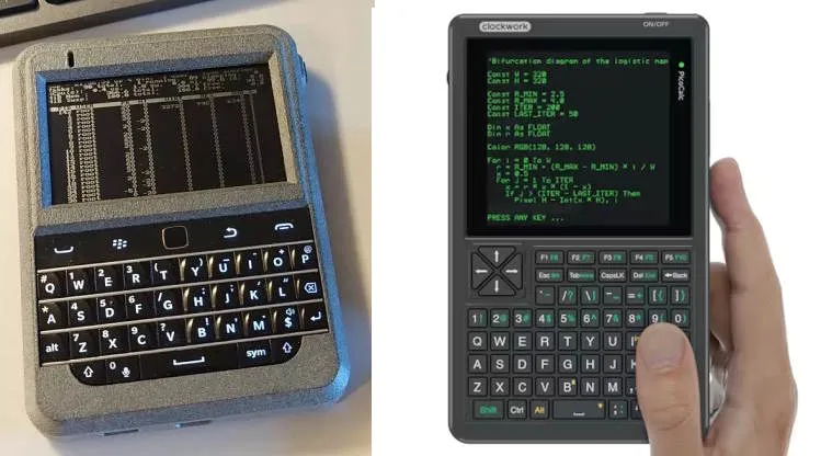
I am not aware of examples of such an implementation in the form of a single board, but there are devices similar in functionality: Beepberry and PicoCalc.
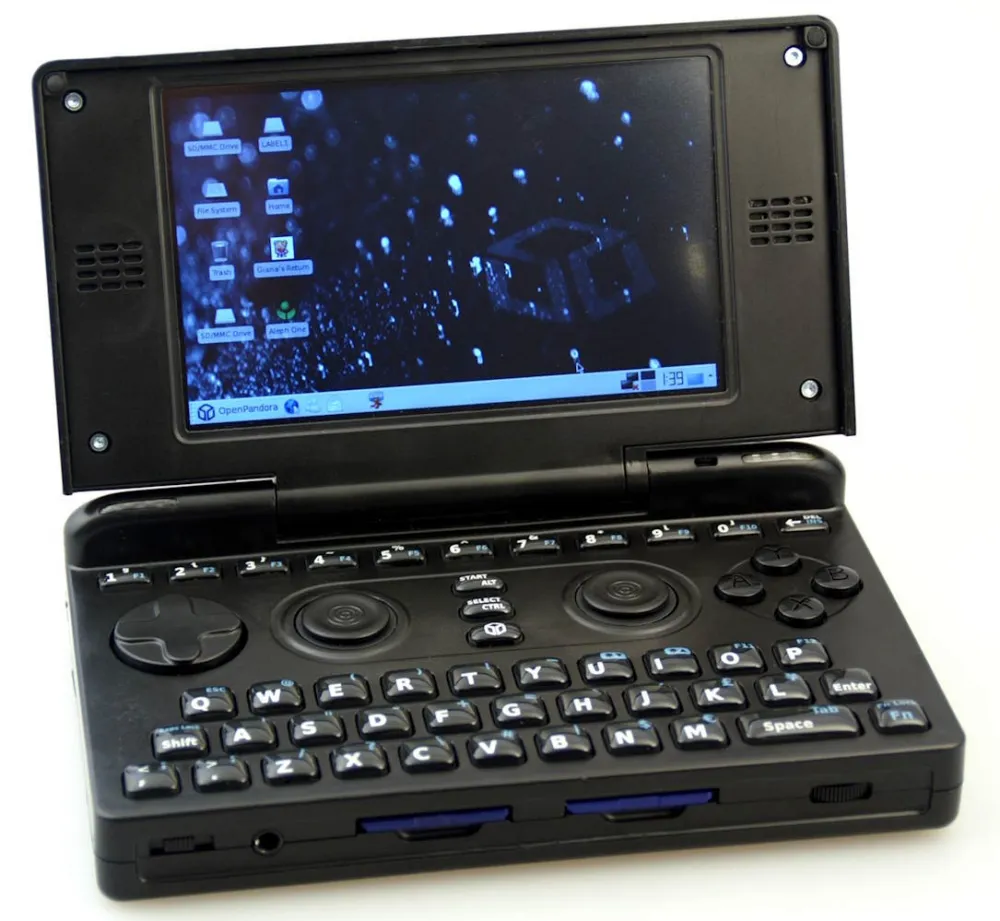
Also, with this approach, the reverse is possible—an advanced device with a complex board and rich peripherals. This task is quite complex and expensive for a hobby project. I know of only one example of such an implementation—OpenPandora.
Core module
The second implementation option is using core modules. Such a module contains the main components: processor, RAM, eMMC, Wi-Fi, and Bluetooth. It takes on the most complex part of the motherboard routing and is entirely soldered onto your main board with peripherals. This approach significantly simplifies the task while preserving all the advantages of custom board design.
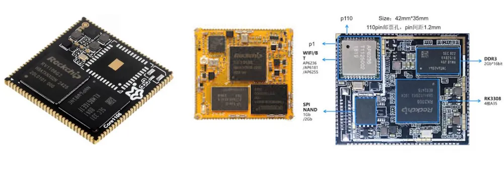
Unfortunately, this option is good only in theory; in practice, it is associated with a number of problems. Such modules are very rarely available for sale. From somewhat popular Chinese manufacturers, there are only a couple of weak models, and for available powerful models, there is no documentation whatsoever.
I have only seen an implementation with such a module in one Chinese device.
Compute Module
The next option is using a compute module. Like the core module, it contains the main components: processor, memory... But, unlike the core module, the compute module is installed on the motherboard via a socket, making it possible to replace or upgrade it. For its functionality and versatility, this layout "pays" with dimensions: the motherboard with a compute module ends up noticeably thicker.
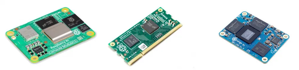
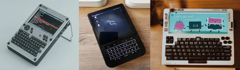
Compute modules are present in the Raspberry Pi board lineup. Such modules have good support and compatibility with various software. Thanks to this, such a configuration is quite popular at the moment. Based on similar modules, there are several portable devices, the class of which has been named 'cyberdeck'. The most well-known devices with such a configuration: uConsole, Hackberry CM5, DevTerm CM4.
Single-board computer
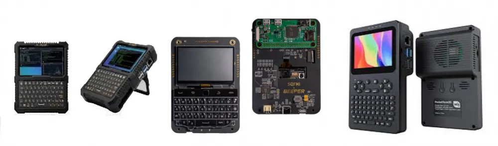
The simplest option is to use a single-board computer as a ready-made motherboard, and additional interfaces can be implemented as separate shields.
Examples: Pi Flux, Beepberry, PocketTerm35.
Peripherals
Portable devices due to their compactness require a special approach to choosing peripherals. You won't be able to 'stuff' a regular monitor and USB keyboard into a laptop.
Display
The issue with connecting the display turned out to be the most complex and unsolved for me. There are several possible approaches for connection:
The simplest option. Connecting the microcontroller to the debug UART interface and outputting console information through this microcontroller.
Connecting a display via the SPI interface. The process is similar to connecting a display to a microcontroller. You can output a desktop to the display or manually draw your own interface from the application. This option is quite simple but inefficient at the same time. Such displays lack sufficient resolution and performance for a desktop, and when outputting information from only one application, the device ceases to be a full-fledged computer.
Output to a display via a cable using the MIPI DSI interface. This is the most correct but also the most complex option. The problem is that this interface is not standardized. Each display line requires its own driver, each display has its own cable pinout, and any documentation is completely unavailable in the public domain. Additionally, you need to provide power for the backlight (~10–20 V).
Output via HDMI. This is a simple and universal way to output an image with good performance and compatibility. However, such a solution turns out to be more bulky and will require an additional converter module, since almost all compact displays have MIPI or a similar interface that needs to be converted to HDMI.
Keyboard
I believe that for a compact standalone device, the keyboard needs to be implemented independently, because otherwise it won't be possible to make the device both ergonomically convenient and compact at the same time.
There are also several options for connecting the keyboard:
USB-HID is the simplest and most optimal option. Many modern microcontrollers support this mode; for them, a large number of examples and libraries are available. For weak AVR microcontroller models (commonly found in Arduino), you can use the software implementation of V-USB at low speed, which is more than sufficient for a keyboard and mouse. This option is also supported by default in Linux and does not require additional configuration.
Connection via the I2C bus using the HID over I2C protocol. This is practically a complete analog of USB-HID, but this option has many unpleasant nuances. There are virtually no open implementations, libraries, articles, or examples for the HID over I2C protocol, so implementing it will require some effort. HID over I2C is supported in Linux, but it must be activated in advance. This means the device will need to be connected in some other way (for example, via UART or SSH), or support must be enabled during the system image preparation stage. Many laptop touchpads and keyboards operate using this protocol, so this option can be used for their direct connection.
Connection via UART, SPI, or I2C with your own protocol implementation. A keyboard is a fairly simple device, and writing a custom script or driver for Linux for it is not that difficult. This approach has two drawbacks. First: the keyboard may not work in the system during boot or in case of a failure, so there must be a way to connect a different keyboard for system configuration or recovery. The second drawback: primary setup and installation of scripts/drivers are required after system installation.
For the mechanical part of the keyboard, there are also several options:
For compact solutions, a keyboard from BlackBerry is suitable; they are available for sale as spare parts.
For larger devices, you can take a ready-made Bluetooth keyboard as a basis and design your own board for its buttons.
For large products, you can use keyboards from various laptops: they come in all sorts of shapes and sizes.
My test bench
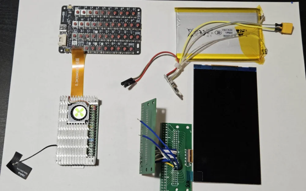
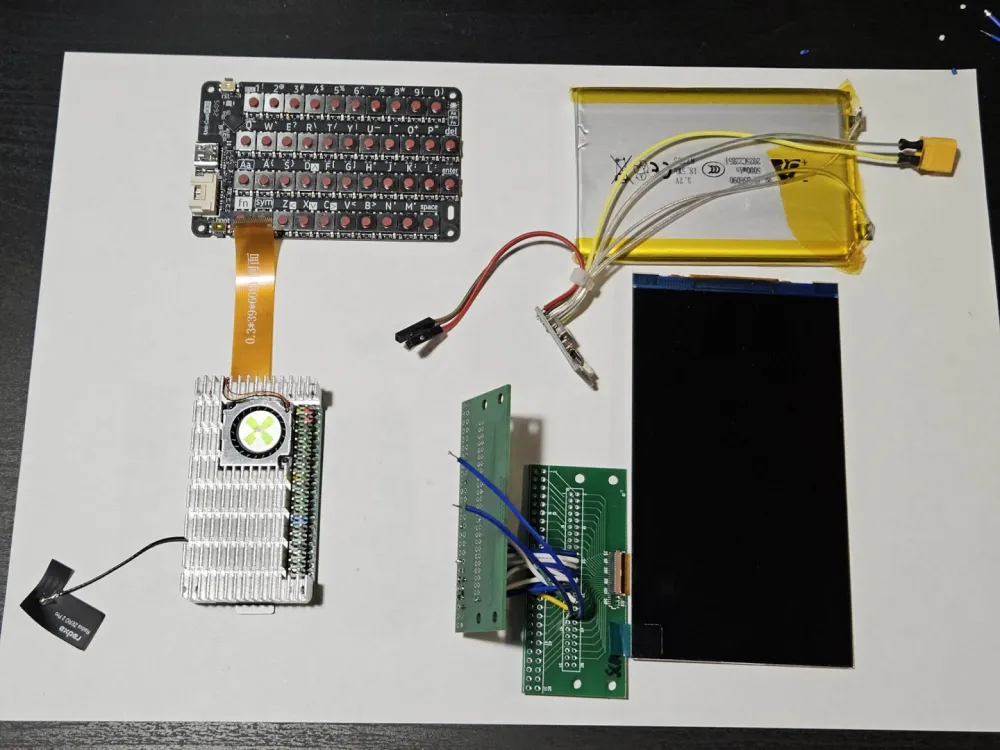
After analyzing the available technologies, I realized that the task of developing my own device remains quite complex and resource-intensive. I decided to simplify the process as much as possible and use a single-board computer in the Raspberry Pi Zero form factor as the motherboard. This minimizes the layout of my own board, and such a format fits well into the dimensions of a compact device.
On my board, I planned to place keyboard buttons, power circuits, a display connection adapter, and a microcontroller that will provide peripheral functionality.
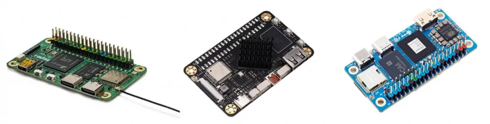
The first problem: out of all the dozens of single-board computers in the Raspberry Pi Zero form factor, only three models support the MIPI DSI interface for displays: Radxa Zero 2 Pro (Amlogic A311D processor), an unnamed board based on RK3566, and Orange Pi Zero 2W. Moreover, two of them differ slightly in size from the standard, and the Orange board is built on an Allwinner processor, which is poorly suited for DIY projects due to weak community support. My choice fell on Radxa Zero 2 Pro.
Choosing a display proved to be even more difficult. I spent a long time researching which options were compatible with my board, which drivers would be available, and looked for screens that had at least some documentation. In the end, I chose a 5-inch screen with an ST7701 driver at a resolution of 480x854, which I planned to connect via a homemade adapter.
For debugging, I chose the M5Stack CardKB II keyboard, which can be reprogrammed for custom tasks.
To power the assembly, I selected a 5000 mAh battery and various 5V power/charging debug boards.
Problems
The first problems were related to the single-board computer. It turned out that my single-board computer has only two USB ports, and it's impossible to bring out additional lines. This greatly complicates connecting a keyboard, memory cards, and other peripherals. Even for debugging, connecting a keyboard and mouse (or a keyboard and flash drive) simultaneously became a problem because the second port works in OTG mode by default, and my tekkix with this board didn't work. When choosing the board, I didn't take this point into account.
The second problem is also related to the board: it turned out to be unpopular. There are few ready-made OS images for it, there's no active community, and with any problem, you find yourself on your own. Moreover, buying such a board is now almost impossible; if a replacement is needed, this will become a serious difficulty.
Additionally, I identified a number of issues in the software part: the mouse cursor on the screen flickers, videos on YouTube play normally in the window, but when expanded to full screen, they start to lag.
The biggest difficulties arose with connecting the screen. Before connecting, I decided to check the pins and found that the pinout does not match the image on the store page on AliExpress where I bought it. After communicating with the seller, he sent me the correct schematic. Then I spent several days configuring the driver on the single-board computer to output the image through the DSI interface. I managed to get signals on the port, but I never saw the picture on the screen. What to do next in this situation, I don't understand. I don't understand what exactly the problem is and how to diagnose it; I lack experience in this matter.
Positive aspects
I managed to compile and run the Armbian image for this board. The board itself works well: its performance is sufficient for solving simple tasks. Additionally, the video core functions correctly - simple games and FreeCAD ran on it.
Also, I managed to figure out the UART, SPI, and I2C interfaces, so there should be no problems with connecting peripherals to them.
I also looked into the board's power consumption. At idle, it consumes approximately 1.4 W (when outputting an image via HDMI), and under load, the peak consumption rises to 5 W. My battery should last for about 7 hours of operation under light load. This is not the best indicator (smartphones are more energy-efficient), but it's not the worst either: this amount of time should be sufficient for comfortable work.
Conclusions
The task, which seemed simple at first glance, turned out to be much more labor-intensive. Designing your own device requires a lot of time, testing, and work with software. When integrating peripherals, many nuances arise that cannot be foreseen at the design stage.


![From Virtual Hands to AI for Survivalists: Curious Open Agent OSes [and One Hardware Project]](https://cdn.tekkix.com/imgs/2026/05/habrcom/big/ce0b1057616faed51cd8b9f3b2b9.webp)
Write comment