- Network
- A
Example of the simplest distributed backbone network
Good day to the community and as they say "congratulations on the start" :)
Introduction
For various reasons, I decided to summarize what I have accumulated over the years and share it with this very community
Format: High Level Network/Security Design (exclusively for professionals)
I am counting on criticism and maybe someone will find it useful.
Well, let's take a deep breath and get started!
Layer 1 Core
Topology
Comments
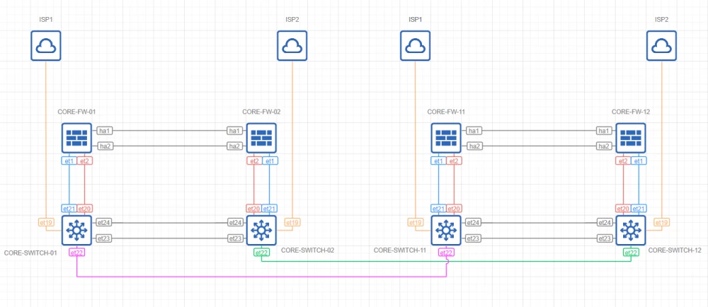
The core is built on the basis of two pairs of MLAG switches with L3 routing support
The network perimeter (as well as zoning) is implemented using two NGFW clusters
The backbone network is a physical ring with two IP channels from two independent telecom operators
External connectivity is provided by 4 IP channels from two independent telecom operators (two for each data center)
Layer 1 Infrastructure
Topology
Comments
Infrastructure channels are built on the basis of two independent cloud operators
Layer 2 Core
Topology
Comments
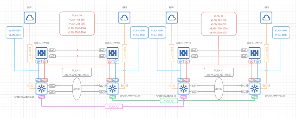
Network core redundancy is achieved through LACP-based aggregation
All interfaces operate in 802.1Q trunk mode
L2 QoS ensures guaranteed delivery of Control Plane protocols
Unused ports are logically disabled and moved to an isolated VLAN
Layer 2 Infrastructure
Topology
Comments
Fault tolerance is achieved through LACP-based aggregation
STP Core
Topology
Comments
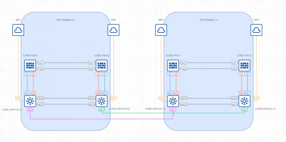
To ensure network stability, the topology is represented by two isolated STP domains
BDPU filters are enabled on all external ports
Comments
To ensure L2/L3 fault tolerance, core switches are represented by a pair of logical MLAG switches
L3 interfaces are built on the basis of VRRP + BFD
L3 peer links are based on SVI
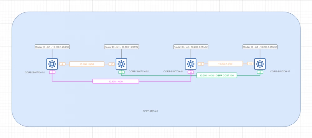
Backhaul Underlay
Topology
Comments
Backhaul underlay is built on the basis of a single OSPF Area 0. MP-BGP is not used in this case due to the lack of need for dynamic frame switching
Flow control is achieved using OSPF priorities
Convergence is ensured using BFD
Security is provided by authentication and access control lists for IP interfaces
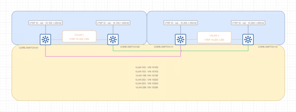
Backhaul VXLAN
Topology
Comments
This topology is represented by a pair of logical VTEPs that allow the broadcast domain to be extended to two data centers. Achieved by means of encapsulation in IP
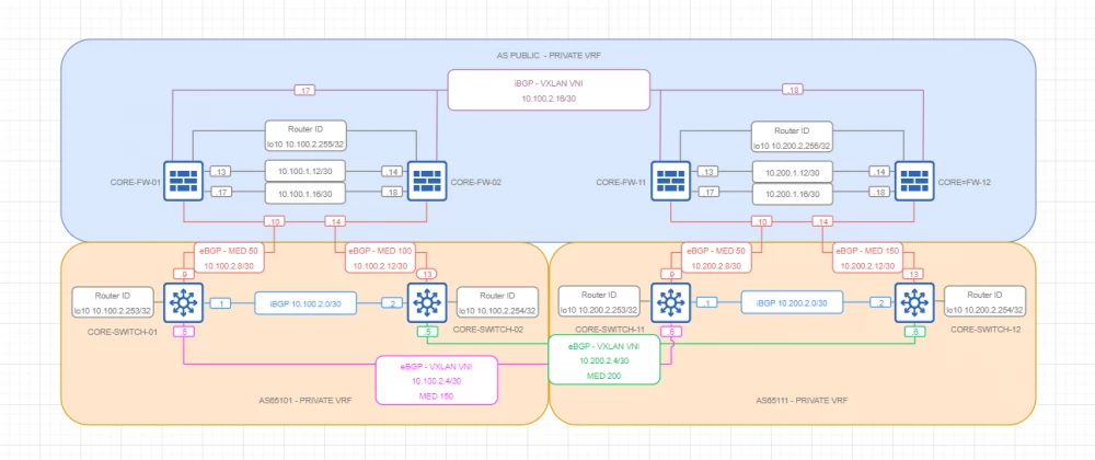
Private VRF BGP
Topology
Comments
The internal VRF is represented by three BGP ASNs combined into a logical ring
One, extended by means of VXLAN and iBGP, between two NGFW clusters and two isolated iBGP ASNs based on L3 switches (one for each data center). The architectural solution is based on minimizing peer links in the core in the absence of BGP RR
Flow control is achieved using MED metrics
Convergence is ensured using BFD
Security is provided by authentication and access control lists for IP interfaces
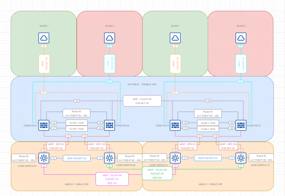
Public VRF BGP
Topology
Comments
External VRF is also represented by three BGP ASNs combined into a logical ring
External connectivity is provided by means of 4 channels from two independent telecom operators
Perimeter control is achieved by means of NGFW. Due to the absence of transit traffic, the external address space is studied by means of the 0.0.0.0/0 prefix. The remaining prefixes (except for the local range) are filtered to improve NGFW stability
Flow control is achieved by means of the MED metric
Convergence - by means of BFD
Security - by means of authentication and access control lists to IP interfaces
Private VRF segmentation
Topology
Comments
The internal network is represented by 5 isolated segments (the minimum required number). Each segment is subject to inspection, identification, IP flow filtering, and user identification.
Private EDGE additionally performs the following functions: (G)SLB and TLS termination; WAF
Private DMZ: WAF, as well as hosting network and front-end services such as Proxy, DNS, SIEM, Web, RADIUS/ISE
Back End: (G)SLB, as well as hosting databases such as LDAP, SQL, etc.
Util: hosts support services such as Netflow, Monitoring probes, Syslog, etc.
RDS: hosts administration services such as RDS
Public VRF segmentation
Topology
Comments
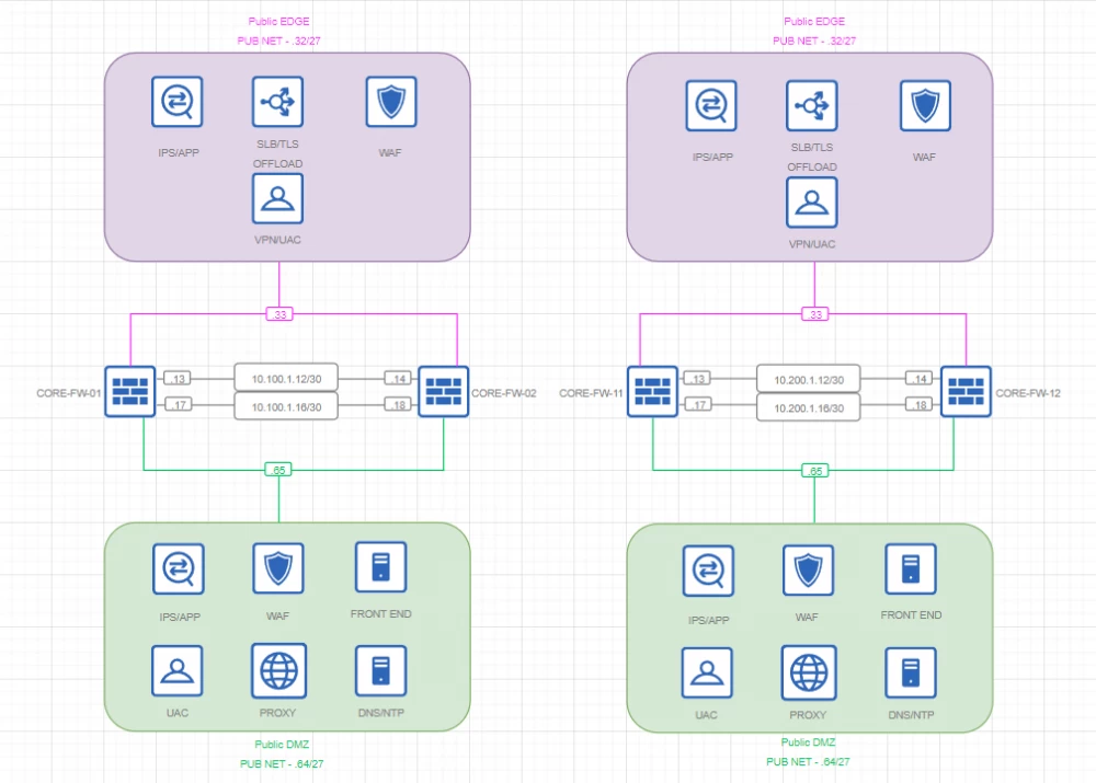
The external network is represented by 2 isolated segments (the minimum required number). Each segment is subject to inspection, identification, IP flow filtering, and user identification.
Public EDGE additionally performs the following functions: (G)SLB and TLS termination; WAF and VPN termination
Public DMZ: WAF, as well as hosting network and front-end services such as Proxy, DNS, Web
Zero Trust
The Zero Trust architecture allows you to manage access at the level of individual servers and switch ports, thereby preventing unauthorized access and potential leaks within the broadcast domain.
In conclusion
Thanks to everyone who read to the end. Waiting in the comments :)








Write comment