- DIY
- A
Hardware Timer as a Microphone
In the development of electronics that includes a sound source, it is sometimes necessary to test for the presence of sound.
What can happen in the field of electronics development. Who would have thought that a timer could be a microphone. However, this is to some extent true.
In the development of electronics that includes a sound emitter, sometimes it is necessary to perform a binary test for the presence of sound. In this text, I will show one of the simplest ways to perform such a test.
Task Statement
It is required to determine the presence of sound in the microphone wire. It is not necessary to determine the frequency, it is not necessary to determine the spectrum. It is not necessary to recognize the signal. You just need to say whether there is sound or no sound.
What is the plan?
Apply sound to the hardware timer of the microcontroller and count the positive edges. If the counter increases, then there is sound. If it does not increase, then there is no sound.
Implementation
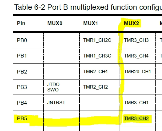
On my at32f435zm microcontroller, a wire from a differential pair that comes from an analog microphone is connected to GPIO PB5. In the microcontroller on pin PB5, I activated the input channel, which clocks hardware timer No. 3 on the second channel.
This mode is called Input Capture. The GPIO pin PB5 must be configured as an input in the alternate function mode Timer 3 channel 2 (TMR3_CH2). This function corresponds to the PIN_MUX value of 2.
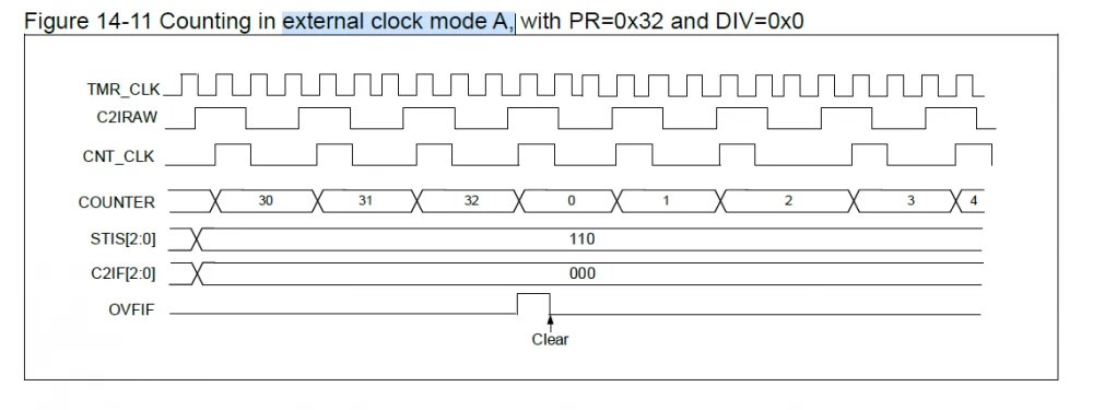
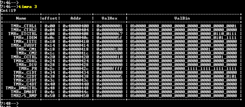
When a positive edge occurs, the counter should be immediately increased by 1. Thus, the hardware timer will count the pulses from the microphone. A small comment on the timer 3 register map settings. The timer should be switched to External clock mode A.
Here are the key settings in the register map:
Register | bit field | value | explanation |
TMRx_CTRL1 | TMREN | 1 | Enable the timer |
TMRx_STCTRL | SMSEL | 7 | External clock mode A — Rising edge of the TRGIN input clocks the counter |
TMRx_STCTRL | STIS | 6 | Filtered input 2 (C1IF2) |
TMRx_STCTRL | ESP | 0 | rising edge |
TMRx_CM1 | c2c | 1 | Input, C2IN is mapped on C2IFP2 |
TMRx_PR | PR | 65535 | maximum count limit |
TMRx_CCTRL | c2en | 1 | Channel 2 enable |
The remaining fields can be left unchanged, as they will be set to the required values by default upon reset.
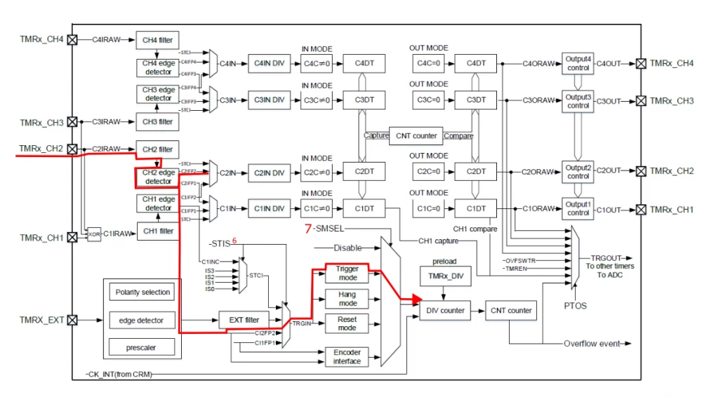
This is the path the clock signal should take from the microphone to the timer.
Debugging
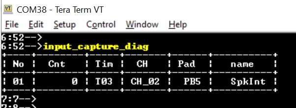
I have UART CLI in my firmware. Therefore, I can debug the functionality separately, in parts. Here in the boot log, a message appeared that the channel was configured.
It can be seen that the GPIO really switched to timer No. 3 channel 2.
The configuration of timer 3 is entirely determined by its registers. Here is a valid config.
There was no sound yet, so the counter is expectedly at zero.
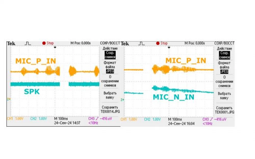
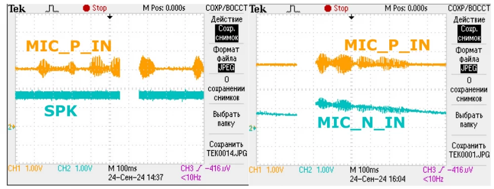
Now let's turn on the melody. This is what a fragment of the signal looks like on an oscilloscope.
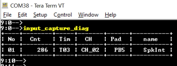
After the melody sounded, it can be seen that the value of the hardware counter increased by 286.
It turns out that the sound sensor works. We can rejoice.
Advantages
++ This is a kind of ersatz technology for those who, for various reasons, cannot use audio codec chips.
++ Simplicity and crudeness. Nothing to break. Such an improvised sensor can be made even on discrete logic.
++ No calculations. No load on the microprocessor. Everything happens completely in hardware. The sound clocks the hardware timer.
++ This is a sanction-resistant way of sound testing.
Disadvantages
--It is impossible to understand the spectral component of the sound.
--It is impossible to understand the meaning of the melody played.
Results
It was possible to make automatic sound detection using a conventional hardware timer.
Glossary
Acronym | Decryption |
КМОП | Complementary Metal-Oxide-Semiconductor |
CMOS | Complementary metal–oxide–semiconductor |
Links
№ | Hyperlink |
1 | Why a microcontroller programmer needs complex numbers (or a review of the MEMS microphone MP23DB01HPTR) |
2 | Logical levels or where zero ends and one begins. |
3 | Review of the Audio Codec NAU8814YG |





Write comment