- DIY
- A
Tetris on ATtiny10
Deciding to use the last days of vacation to bring my stock of electronic components to some semblance of order, I came across an unknown SOT-23-6 chip with barely readable markings.
Thus, the idea of Tetris was finally formed.
Electronic part:
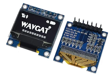
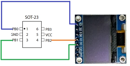
I decided to connect the LCD display via the 3-SPI protocol. The protocol differs from the usual SPI in that the D/C value responsible for selecting data or command transmission for the display is transmitted by an additional zero bit in the SPI transaction. This allows not to connect the D/C pin.
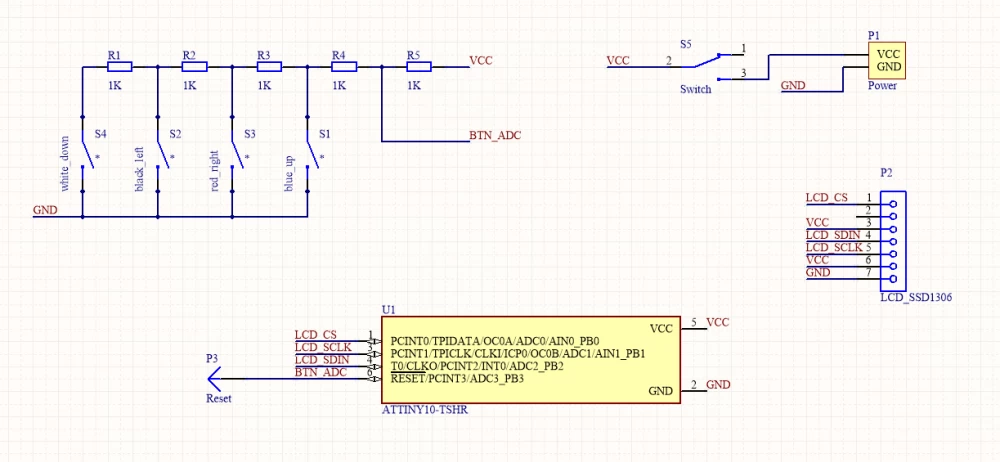
The display connection diagram turned out as follows:
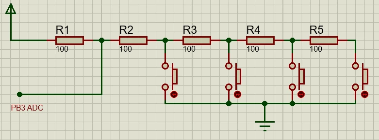
After connecting the display, the microcontroller has only one free pin PB3, to which at least four buttons need to be connected. The solution in this situation is to use PB3 as an ADC input for the following circuit:
The presence of the divider is due to the fact that PB3 is also a reset signal and the voltage on it during normal operation should not fall below 0.9V. Of course, it was possible to disable the external reset using the RSTDISBL fuse, but in this case, I would lose the ability to reflash the microcontroller, which, by the way, I had only one.
As a result, the following general scheme was obtained:
Power is supplied by a tiny 3.7V, 180mAh lipo battery connected to the P1 connector. The battery turned out to be the only element I had to purchase for this project, and according to the seller, it has built-in over-discharge protection. For this reason, there is no discharge control for the power source in the circuit. Also, there is no separate programming connector in the circuit, except for the PLS pin for RESET. Part of the programming signals (PB0 – TPIDATA, PB1 – TPICLK) are connected through the P2 display connector. The display itself is removable and docks through the PLS.
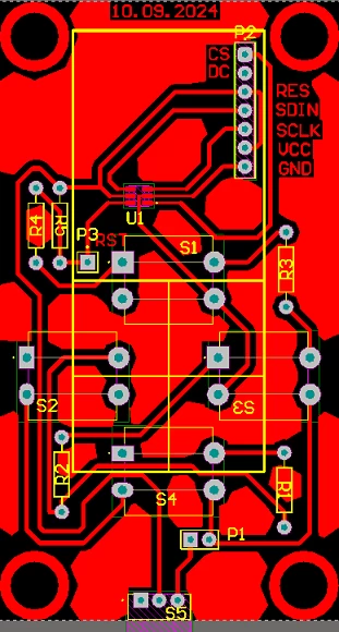
This is what the board looks like after routing:
The board was easily transferred to single-sided PCB and in my opinion, the approach to simplify the circuit as much as possible fully justified itself.
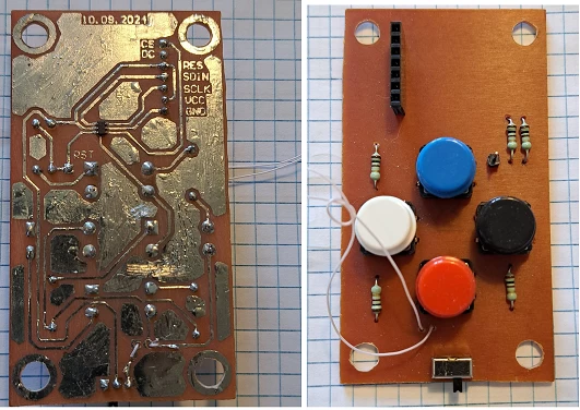
After mounting all the components, the following was obtained:
Software part
Given the limited resources of the Attiny10, all the software is implemented in assembly without using third-party libraries.
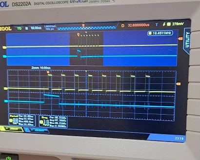
The first thing I did was get the ADC values for button presses. To do this, I wrote a separate program whose essence is to constantly read the ADC values and output these values to the GPIO in the form of an 8-bit packet. In order not to waste time receiving data, I simply connected an oscilloscope to the necessary GPIO and thus read the necessary ADC values.
For example, this is what the packet looks like when the UP button is pressed:
Having received the values for button presses, I proceeded to write the main logic of Tetris, which can be divided into the following key points.
Working with the display
All objects displayed on the screen are stored in the microcontroller's SRAM, and given the volume of 32 bytes, scaling is indispensable here. Therefore, the minimum display unit will be an 8x8 pixel square, resulting in a game field of 8x16 squares. Since the display is monochrome, one bit is enough to store the value of a square. As a result, all objects displayed on the screen fit into an array of 16 bytes. To make it clearer, here is an example:
0 - 00010000
1 - 00111000
2 - 00000000
……………...
15 – 00000000
uint8_t t_field[] = {0x10, 0x38, 0x00, 0x00, 0x00, 0x00, 0x00, 0x00, 0x00, 0x00, 0x00, 0x00, 0x00, 0x00, 0x00, 0x00};
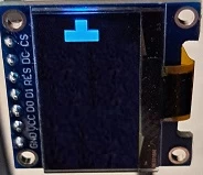
The zero byte of the array corresponds to the first line of the game field, 15 — to the last. Here's what it looks like on the display:
The display itself operates in horizontal addressing mode, which allows for easy image updates by simply sequentially transmitting data, with page incrementation occurring within the display itself.
Drawing elements
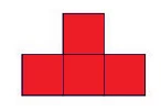
To simplify the drawing task as much as possible, I define each element with an 8-bit pattern. For example, for the element
the patterns will be as follows:
Each inner square contains the bit number in the pattern. The rotation point is in the center. The structure describing the current element contains the following fields:
brick_x coordinate x
brick_y coordinate y
brick_rot position relative to the rotation point
brick_type type of element
The advantage of this approach is that the code volume is significantly reduced as all elements are processed in the same way.
The disadvantage is that it is impossible to set an element consisting of a straight line of 4 squares. As testing has shown, this is quite significant, and perhaps in the future I will add this element using a separate drawing, since there is still space in the microcontroller.
Pseudo-random and some implementation details
I made the random based on a combination of button press events and a free run counter changing by a timer. It turned out not perfect but quite playable.
After turning on the power, a splash screen with the inscription PUSH is displayed on the screen, the difference in time from the appearance of the splash screen to pressing any key ensures randomness in the choice of the initial figure. A counter is provided to count the results. Each time a filled line is removed, the counter increments by one. Initially, I wanted to display the result in the last line in the form of binary code, but in the end I abandoned this idea, it looked strange and confused the player. The counter found another use: the pause between element shifts down is initially 0.7 seconds, as the score increases, the pause changes as follows:
counter: 0..15 pause 0.7
counter:16..31 pause 0.6
counter:32..63 pause 0.5
counter: > 63 pause 0.4
As a result, as the game progresses, the speed of falling elements accelerates, adding additional complexity.
The sources were compiled in Atmel Studio 6. The entire firmware takes up 898 bytes.
Case and assembly
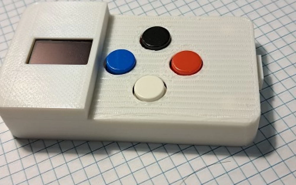
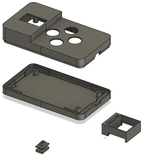
For a complete device, a case is needed, and this case probably became the most difficult part of the project. I tried several options, spent meters of filament, and eventually managed to create an acceptable option:
To create the 3D model of the case, I used Fusion 360, printed on a Flying Bear Ghost 6, material PLA.
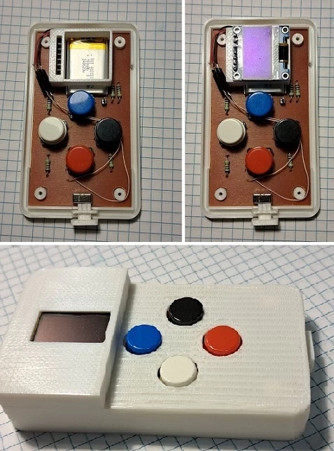
Assembly process
All sources and materials for the project are available at the link:
https://github.com/staticbear/attiny10_tetris



Write comment