- DIY
- A
Development of a stepper motor control controller
Development of a stepper motor controller
Background of the question
A colleague, a talented designer, sometimes develops unusual things. Such things are usually not available on the market, or they exist but with worse parameters or at exorbitant prices. For one of his developments, an inverter was required to control a stepper motor. In addition, a small controller was needed to implement the logic of the device. If the inverter can still be found on the market, although it is not so simple, and why - I will explain below, then the controller, no matter how you look at it, has to be developed by yourself, here are completely individual wishes and logic of work. And here at the coffee point, I was the person who had heard something about electronics. After a couple of cookies and a faceted glass of latte, we discussed the preliminary terms of cooperation.
In most cases, when people come to me for the development of some products, they do not always know what they want and what they need in the end. At best, they can at least provide a structured description. In this situation, I was provided with a fairly good description, practically, a technical task, in its historical understanding. It was a well-designed document with a detailed description of everything desired, with sketches of some parts and block diagrams. Quite quickly, in one or two meetings, over a couple of glasses of tea, we agreed on all the requirements for the developed unit.
Goal and means
I will describe the main stages of the "big journey".
1. The system has two motors. The first is a power (5kW) BLDC with an existing VESC controller. The second, which needs to be controlled (weaker), is a stepper motor.
2. Each motor has an encoder. The "speed" and "position" values need to be read from them.
3. The developed unit will work together with the VESC controller. Interaction via the CAN bus.
4. The speed of the stepper motor should be adjustable: 0 - 850 rpm.
5. An option for "isolated" operation of the developed unit from the VESC is required. That is, the rotation of the stepper motor needs to be adjusted depending on the encoder readings from the traction unit shaft on the VESC.
6. A variant is needed where the motor speed is calculated in the power inverter. This speed is transmitted to the control board being developed via CAN.
7. Implement work with two encoders: one or two.
8. Implement support for two limit switches.
9. System supply voltage: 72 V.
10. RS232 and RS485 are required for external communication and control of the installation (one to choose from).
11. Implement a standard STEP/DIR interface with galvanic isolation.
12. Install three LEDs to display statuses.
13. Install 4 switches to select the operating mode.
14. Try to develop a prototype for contract assembly in friendly China with one of the electronics manufacturers.
15. Develop a block that is cheap to manufacture in small series.
This is a summary of a large technical specification with pictures and blackjack so as not to publish a text here that takes 15 minutes of careful reading.
Technical Specification Analysis
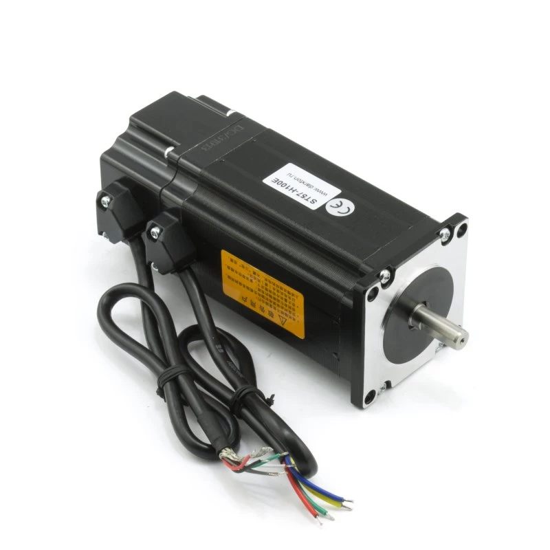
The stepper motor was mentioned in the technical specification – it is ST57-100E. The torque it should provide and the speed are also given. Well, classically, the use of an H-bridge to control each winding is seen. The driver and keys will be selected later in the process of detailed circuit development and after calculations. An approximate estimate gave a very low current frequency (something up to 5kHz, which does not scare me at all). But the voltages and currents immediately seemed high. Detailed calculation is needed.
Interface part.
CAN, RS232, RS485 are not particularly worth considering, just remember that UART is needed for them on the controller and choose cheap Chinese microcircuits from those that you are confident in. And it will be perfect if their supply voltages also match the controller's supply voltage.
STEP, DIR interface. I heard something about it, 5 minutes of reading on the internet and I realized that there is nothing particularly complicated here either. Galvanic isolation is needed – an optocoupler.
Install two limit switches. In general, sensors come with npn and pnp outputs, so I will provide for the possibility of connecting any types (I am sure that someday they will buy or install the wrong sensors), and short-circuit protection (just in case).
Encoders. One encoder is normally installed on the stepper motor, the second one is purchased. It is pleasing that their power supply is the same — less work already. The encoders have differential signal outputs, standard incremental signal outputs A and B, and one also has a full revolution mark Z. For such solutions, the standard solution on the AM26C32CD immediately came to mind, by the way, it is also powered by +5V and, of course, of Chinese production. I will probably use them. It will also be good practice, as with limit switches, to provide short-circuit protection for the power supply.
Switches and indication remain, there are no questions at all — let the customer choose what they like best in appearance, and my job is small — to draw them on the diagram to the controller.
A little math
After analyzing the terms of reference, I began to study the dark points (not matter, but a pity).
The most important thing seemed to be to determine the parameters of the motor driver, everything else was considered insignificant.
The main thing that needed to be done was to calculate the motor parameters. Almost all blocks that control motors have some features. They are related to the required parameters. It is important to take into account what speed and what power is required from the motor. This will determine what current needs to be supplied to the motor windings. And the speed will determine what voltage we will need to have with these current parameters. Normal documentation provides graphs of torque versus speed. Sometimes there are also current graphs, but more often they are given at the nominal current of the windings.
As far as I know, stepper motors are divided according to different parameters and designs, but there are three main groups: with a permanent magnet on the rotor, with a rotor made of a special alloy that is magnetized during operation (variously called: reactive, with variable magnetic resistance) and hybrid. I have a hybrid one here, which has 200 poles. In general, the topic is interesting and there is a lot of information on the Internet.
Next, I know that motors have two divisions according to the structure of the windings: unipolar and bipolar. I have been given a bipolar one. For me, this means that to control it, I need to make a full bridge. That is, I must ensure the movement of current in different directions in each winding.
Next, you need to understand how to power this motor to get the required speed with the required torque.
I need to make it spin at a speed of up to 850 rpm. To find out how many steps per minute I need to get from it, multiply the number of its steps per full revolution by the desired number of revolutions per minute.
850 (rpm) * 200 (steps/rev) = 170000 steps per minute.
After that, I determine the required control frequency in kHz. To do this, I find out the number of steps that need to be taken per second. And then I divide by a thousand (otherwise it will be in Hz).
170000 (steps/min) / 60 (sec) = 2833.3(3) (Hz), that is, 2.834 kHz maximum.
Next, I add a little physics to the math. I find out what will happen to the resistance of the motor windings with alternating current of a given frequency (this is something about reactances, impedances...):
R(L) = 2*π*f*L
f – frequency applied to the inductance coil (our motor winding)
L – inductance of the inductance coil
2*π=6.28 ?
In general, this calculation will not give a super accurate result, since the engine is a more complex system (not an inductance coil), with a common core, in which electromagnetic fields behave cunningly when the rotor rotates, and the stator itself - the core uniquely affects the process. BUT this calculation provides enough information to design the motor driver and understand what currents and voltages I need. For a more complete picture, you can use the Maxwell from ANSYS program, if you, of course, have enough money to buy it and enough time to master it.
2*3.14*2800 (Hz) * 0.0026 (H) = 45.7 (Ohm) - the reactance of the motor winding.
And I also have active resistance, which is easy to forget about at such reactive values, but it is better to take into account:
45.7 (Ohm) + 0.8 (Ohm) = 46.5 (Ohm) - the total resistance of the motor coil.
According to Ohm's law, to get the required current in the coil (well, to get the torque I need), it is necessary to apply to it:
U = R*I,
U = 46.5 (Ohm) * 4.2 (A) = 195.3 (V)
As much as 195V, not small values.
After this simple math and no more complex physics, you can start developing the driver.
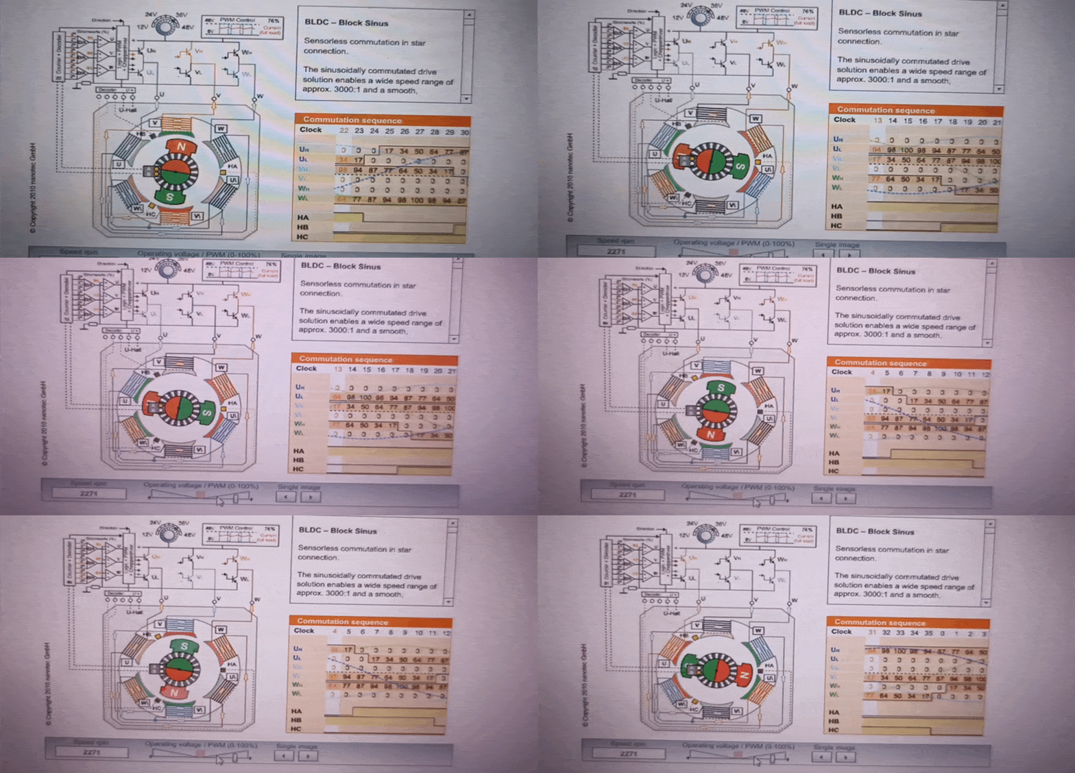
There is an excellent online visualizer from the respected nanotec, which demonstrates the operation of motors, drivers and even feedback.
There are many options for both stepper motors and BLDC, as well as many options for their connection. You can adjust the rotation speed, you can go through the steps and see what values should be on the control system. This tool will help both professionals and beginners understand the principle of operation and more quickly implement their driver.
Development of circuitry
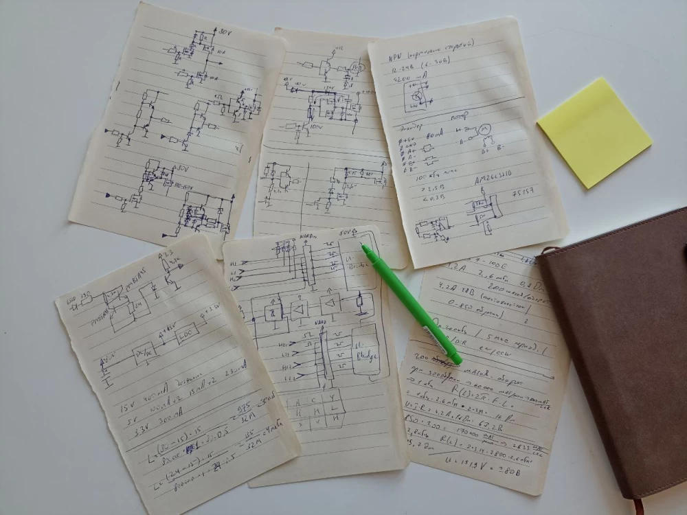
I love drawing flowcharts before starting to develop anything. The initial one was provided in the terms of reference by the customer (but that was a general flowchart of the device), which, by the way, helped a lot to understand the essence of the project. Then I draw a bunch of different functional blocks in a notebook and connect them with arrows. And when there is already a solution that satisfies the terms of reference and my aesthetic paradigms, I draw it in a clean copy. Here's what I got:
By the way, Altium allows you to add almost any logo to the project board in a few clicks. The main thing is to choose the right silk screen layer. In older versions of the program, a special script had to be used, but now it is enough to simply copy the image to the clipboard and then paste it into the board project.
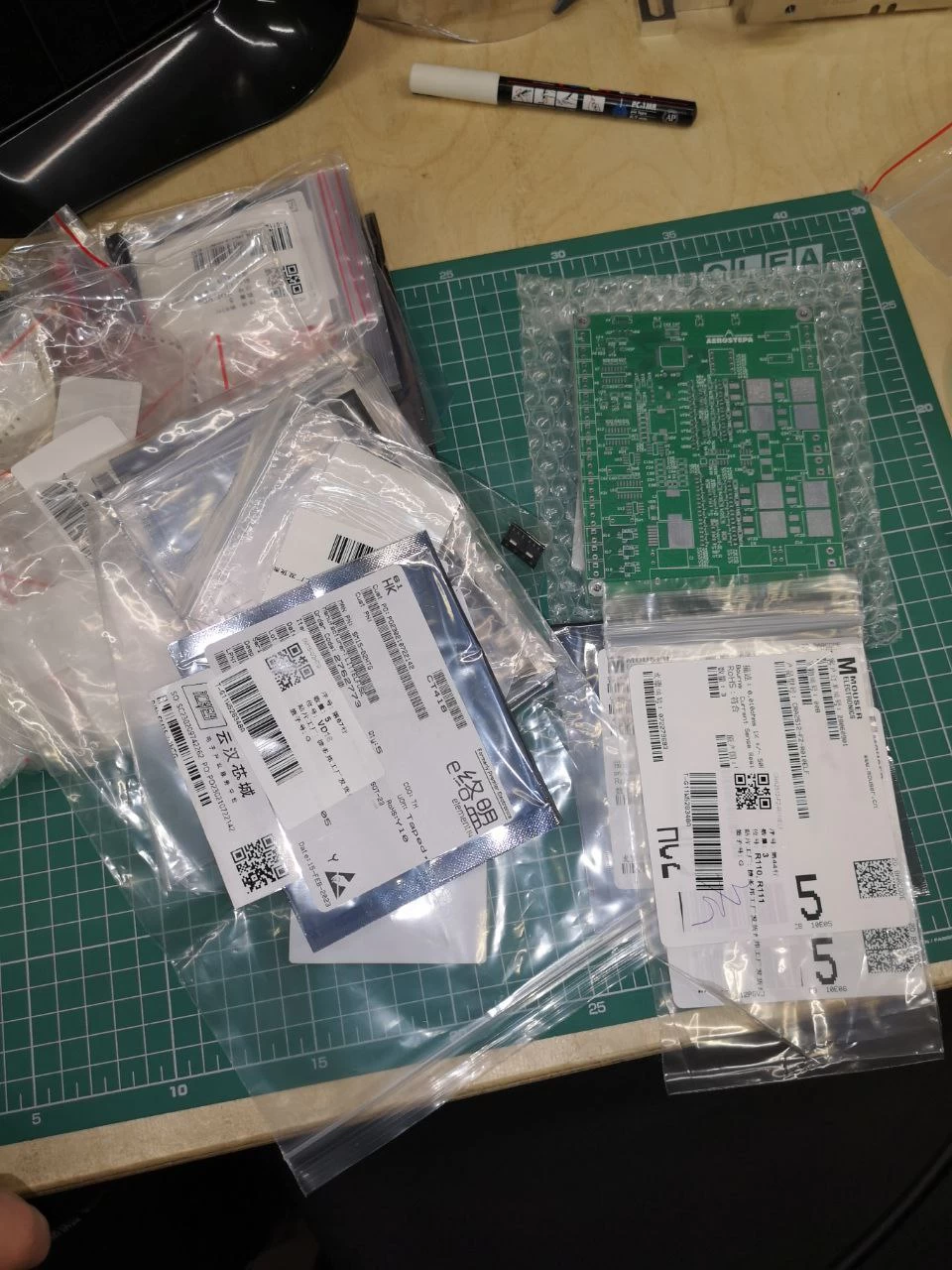
This is what a package from China looks like. We see the board and elements in bags. Everything is laid out wisely, conveniently - as for people...
Block assembly
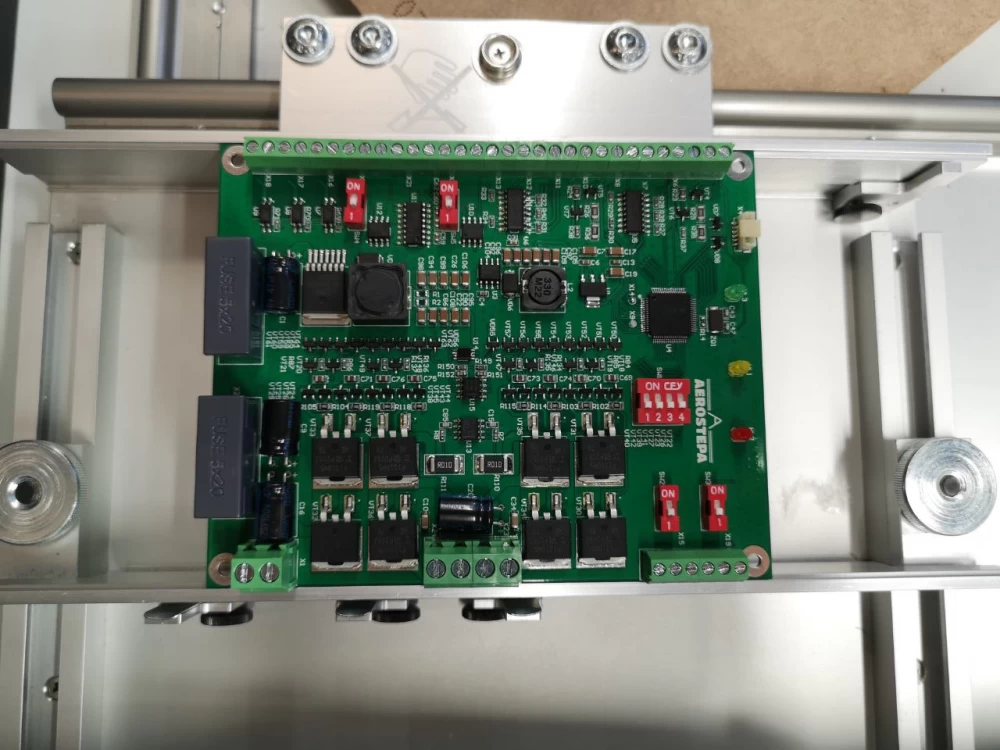
The blocks were assembled manually, but using time-tested technologies. Without a solder stencil, but the paste was applied with a dispenser and the components were installed on it manually with tweezers. After that, the block went to the oven for reflow. The result - fresh out of the oven - top class!
After the oven, the leaded components were delivered with an ordinary soldering iron.
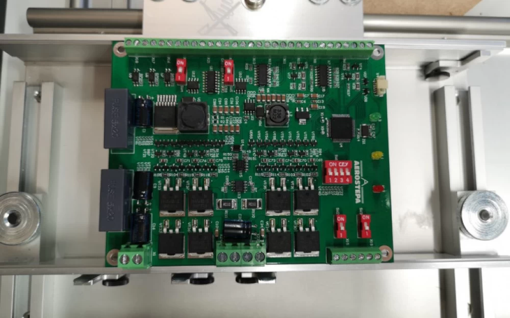
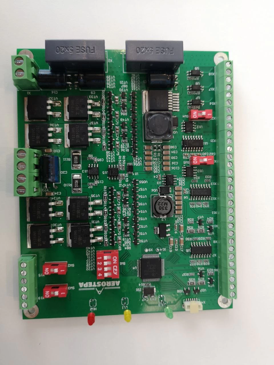
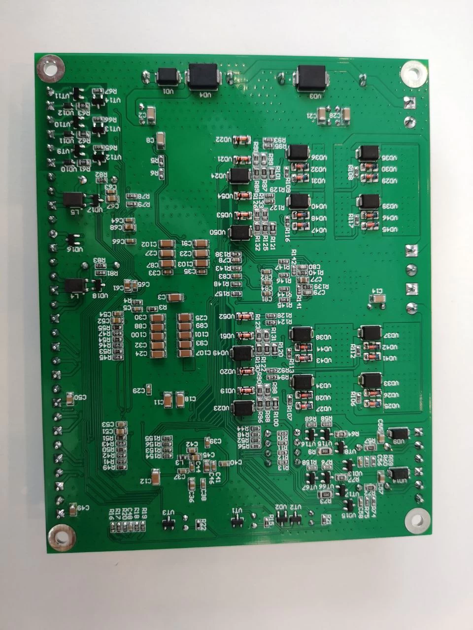
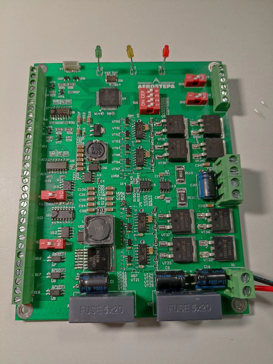
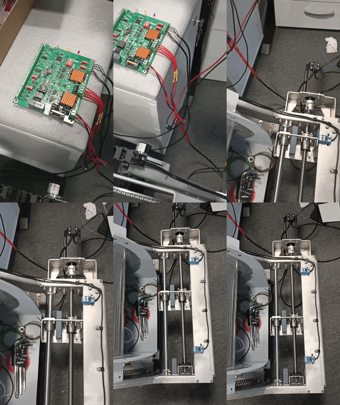
In the end, after assembly, the block looked like this:
After assembly, the control stage begins.
First, visual inspection: everything is in place and nothing has shifted. Then the responsible circuits are checked with a multimeter for short circuits (power, high voltage lines, high current lines). And only after that the block goes to commissioning.
Commissioning
First, the supply voltage is applied from the laboratory power supply with a low current limit. The power supply voltages are checked to see if they are normal. I check them with an oscilloscope and immediately monitor their ripple.
Microcontroller
As mentioned above, surprisingly, the chosen and embedded in the circuit was not a Chinese Artery or WCH or any other from Giga, but an American 32-bit microcontroller based on Arm Cortex-M4F.
This is due to 4 reasons:
Firstly, I know it, and launching the block on it is super simple and fast. It has been used repeatedly and has performed excellently. The entry threshold to it and the environment is extremely low. The environment is free and convenient.
Secondly, this electronic block was developed at the end of 2022, when the silicon crisis + sanctions made the beloved STMs some fantastically expensive rarity, and the stubborn statements of ST directors also undermined the faith that their products should be used in small-scale devices. And these controllers, I don't know why and how, are still in abundance in warehouses and are easily purchased in the Russian Federation. On Elitan, Aliexpress, and in the JLC, PCBway warehouse, they are available in thousands. At the same time, their price is about 5-6$ for a single purchase. How this happens - I don't know, but this arrangement suits me.
Thirdly, these controllers have all the necessary interfaces, and if you look deeper, even more. For example, here's what we see in the PWM description: "advanced control, including: eight pulse-width modulation generator blocks, each with one 16-bit counter, two PWM comparators, a PWM signal generator, a dead zone generator, and an interrupt/ADC trigger selector; two low-latency shutdown PWM inputs; two quadrature encoder interface (QEI) modules with a position integrator for tracking encoder position and determining speed using a built-in timer." That is, even the two encoders that I have in the block will be super convenient to start and will almost not consume software resources. I'm not even talking about simple control of two H-bridges. Datasheet, for those who can still open the Texas Instruments website.
Fourthly, their errata is excellent and complete, and the community has gathered ready-made implementations.
For Texas controllers, there is a program similar to the cube from ST. It helps to make pinout on the controller and generate an ioc file from it. It also helps to take into account some possible problems when writing the program further, when suddenly some interface does not remap.
To work with the program, you don't even need to read the instructions, such an excellent job was done by UX designers. What to click where is understood intuitively. The entry threshold is probably 5 minutes. This is what the pinout looks like in my project:
And after this revision, the board began to work stably, which is what I expected from it.
What's next?
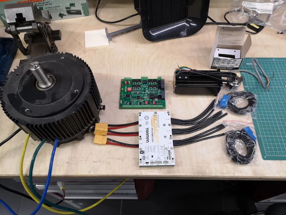
Now we have a working board and several control options. Here is a set of everything for the project.
I think this project has interesting prospects, although the demand for it is definitely not high. Well, for now, I'm waiting for the debugging process to be completed and will slowly catch the bugs of the electronic unit so that everything will be fine in version 2.
Maybe something else will change, but this, as they say, is a completely different story…




Write comment