
- DIY
- A
How to Increase Voltage?
In the previous articles, we examined interesting high-voltage devices, mainly of the electrostatic kind — electrophorus machines: school models, Van de Graaff generators, etc.
We even looked at a mechanical voltage transformer — quite an astonishing device in its own right.
However, if we turn to more practical (and equally interesting) matters — let’s ask the question: “if not electrostatics, then what?” :-)
How can we increase voltage if we wanted to do it in one of the simplest ways and make it practically applicable?
There is nothing simpler — we just need to refer to an invention that is over 100 years old, which, despite its age, is still actively used in electronics — and we will talk about voltage multipliers.
The first voltage multiplier, or to be more precise, “voltage doubler,” was developed back in 1914 by Heinrich Graetz, who later proposed a cascading scheme for it, enabling multiple multiplication.
Despite the fact that the initial idea was presented by the author above, the device entered history as the “Cockcroft-Walton multiplier,” as they applied it for a significant practical purpose — the splitting of the atomic nucleus (1932), for which they received the Nobel Prize, and the device itself entered history not under the name of the first inventor, but under the name of those who brought it fame...
But, all this happened much later... At that time (1914...1920s), the device had already become a breakthrough in its field, as there were problems with creating high-voltage transformers that were sufficiently reliable (and, if possible, compact) to deliver voltages in the hundreds of kilovolts — this was a rather complex technical challenge, where, moreover, appropriate rectifiers were required for practical purposes, and all together, this was (partly due to cost, not just technical complexity) quite burdensome for most laboratories working in the field of physics.
The problems were related to the fact that at that time, there were still not enough reliable materials capable of withstanding high voltages in the hundreds of thousands of volts for a long time: for example, the practice of using transformer oil was just beginning to come into use, while alternative options, like air insulation, required too great distances between current-carrying elements, which reduced the efficiency of the transformer while increasing its size (the dielectric strength of transformer oil exceeds that of air by about 4 times on average, which allows for a significant reduction in size without the risk of breakdown), there were also issues with other components.
However, the main problem was lurking in the area of rectifiers: the existing solutions at that time, such as mechanical rectifiers — which were electric motors that mechanically closed contacts during rotation — resulted in significant losses (due to sparking and more), could only operate at low frequencies (50 Hz).
Thus, in fact, it was impossible to achieve high voltages in the hundreds of kilovolts with their help.
Alternative technologies, such as electrolytic rectifiers, required a huge number of cells, which, accordingly, implied large dimensions, and did not differ in reliability (low overload capacity, low thermal resistance).
Therefore, the proposed solution became a breakthrough — it suggested creating a very simple high-voltage generator that was compact and reliable.
What this solution entailed: it was proposed to use a series charging of capacitors, with voltage addition.
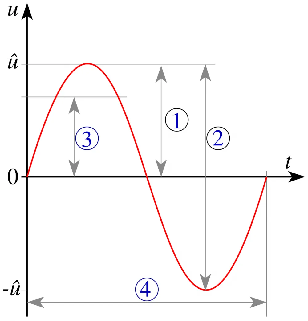
To begin with, to understand how this works, let's look at what a "wave period" is: this refers to a complete oscillation during which the system returns to its initial state — in the illustration below, it is indicated by the number (4).
Accordingly, a "half-period" (or, in other terminology, a "half-wave") will be called half of this complete oscillation — in the illustration below, this is the section of the sine wave located above or below the axis t:
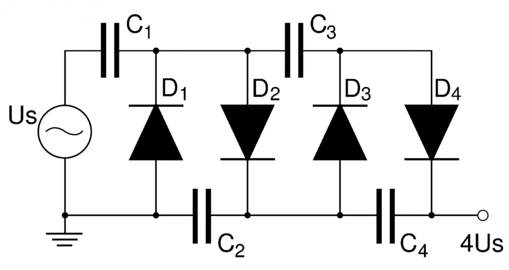
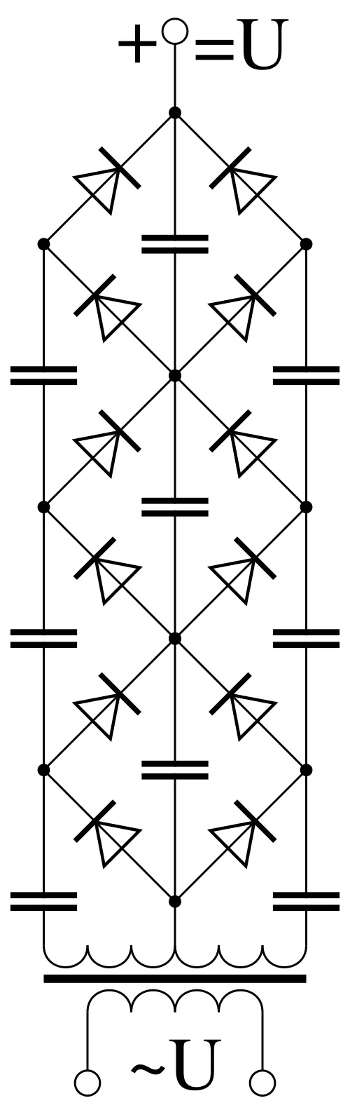
Now, let’s turn directly to the assembly of the multiplier, which is usually depicted in the diagrams as in the "header" of the article, or like this (this second diagram is actually more convenient for us, as it makes it easier to understand the working principle described below):
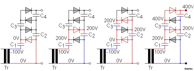
Now, let’s see how it works (the part of the circuit that is activated at each stage is shown in red; we read from left to right):
So, the very first thing we see here is that the circuit is powered by alternating current, meaning that the polarity of the power source changes over time.
The second thing is that we see the diode on the diagram is represented as a triangle, where the direction of the triangle towards the line indicates the direction* that the current can flow through it:
*In the context of the words “in what direction” the current flows, I suggest considering the fact (in case anyone is not aware ;-) ) that positive and negative denote the poles of potential difference, where positive is the area of electron deficiency, and negative is the area of electron surplus. And, theoretically, “if something flows from somewhere — to somewhere, it should flow from surplus to deficiency, not the other way around”! :-D
Think about it, Google this point. It’s interesting :-)))
Thus, if we return to the picture a little higher, with the operating principle, we see in the leftmost image that the alternating current is in the area of the positive half-wave and flows through the diode, charging the capacitor C1.
Next, when the positive half-wave ends and transitions to the negative half-wave (the second image from the left) — the current can no longer flow through the first diode, and it begins to flow through the second diode below, charging the capacitor C2, during which the capacitor C1 discharges and, as we can see, at this stage there is a doubling of the initial voltage — and if we received 100 V from the source, then at this stage we already have 200 V (as shown in the picture).
Next, we look at the third image from the left: there we see that we have again transitioned to the positive half-wave, and here we immediately see that two processes are occurring simultaneously: the charging of capacitor C1 — from the power supply, along with the simultaneous discharge of capacitor C2 and the charging of capacitor C3.
In the fourth image from the left (here we are again in the zone of the negative half-wave), we see that two processes are once again observed: the charging of capacitor C2, the discharge of capacitor C1, and the discharge of capacitor C3 to the load — where the output voltage is already 400 V.
Thus, we see that with this scheme, at every moment in time, it is powered by the half-wave of the power supply, where a kind of "running wave of charge/discharge" is observed, with voltage doubling at each block of capacitors and diodes.
And the multiplication of the voltage at all stages occurs due to the series connection of charged capacitors with the power supply.
The main advantage of such a scheme lies precisely in what it was developed for: eliminating heavy, expensive (and, as we have seen, problematic for a number of voltages) transformers, with the aim of replacing them with a very compact and inexpensive device.
The working voltage that can be achieved with this circuit is arbitrary, within certain limits*, and depends only on the number of "stages," which refers to an assembly of two capacitors and two diodes—we saw this clearly in the picture above, with the principle of operation, where essentially, we could limit ourselves to just the first block of four components, at the output of which a doubling to 200 V occurred—that block is the necessary minimum stage.
*In practice, too many stages lead to the entire circuit becoming prone to pulsations because the capacitor charging process is not instantaneous and takes some time due to their resistance.
To eliminate this potential problem, the circuit is powered not from industrial frequency current (50 Hz), but from a separate high-frequency high-voltage transformer, which allows reducing the dimensions of the circuit itself by using low-capacitance capacitors that can operate at such frequencies.
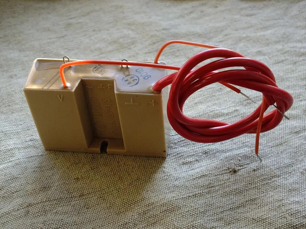
I remember, back in the day when I built a homemade photocopier (yes, it was a strange idea! :-)), I used the flyback from an old television as a high-voltage source, to the output of which a multiplier like this one was connected (only mine was "blue" :-D; below we see an assembly of the multiplier, in a plastic case, filled with compound)—and the spark "shot out" at least 10 centimeters:
For powering the flyback, I used a blocking generator circuit (if memory serves) on a powerful transistor.
I was aware of the dangers of multipliers, so I set a high resistance at the output to prevent a large current from flowing through the discharge (people seem to recommend using an RCD — Residual Current Device, but I’m not familiar with that, I need to clarify this point in more detail) — as WORKING WITH MULTIPLIERS IS VERY DANGEROUS FOR LIFE!!!
You should always keep this in mind and familiarize yourself well with the topic through specialized literature, or better yet, don’t get involved at all — you’ll be safer ;-)
Why did I even need a high-voltage source for the xerox: it’s very simple: to power the korotron — the wire for the corona discharge.
Actually, I overdid it a bit there — ideally, I could have limited myself to a line generator, but “we don't take the easy way,” so a multiplier also appeared in the process :-))
However, let's return to our question...
The discussed voltage multiplier circuit is not the only possibility, as we saw that only one half-cycle of the wave operates at any given moment, therefore, at least one more option for a two-half-cycle multiplier was developed. Try to figure out how it works by yourself:
For most of us, it's unlikely that we will ever encounter a multiplier, at least unless your project requires it — and if it does, surely it will be quite interesting and unconventional :-)
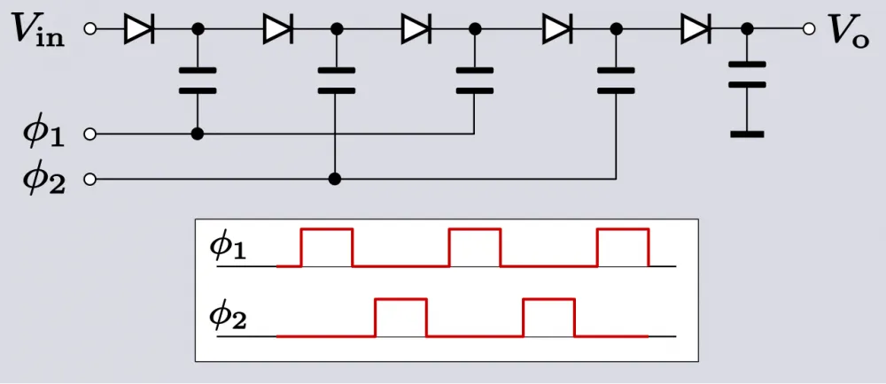
Nevertheless, there is one type of multiplier that we all encounter without even knowing it — used as a micro version (in integrated circuits) for constant voltage, essentially representing a variant of a kind of dc-dc converter (Dickson charge pump), where the voltage is increased to another level, and this can be used in different parts of the integrated circuit as a compact means of flexible power management to reduce energy consumption.
For example, below is a diode version:
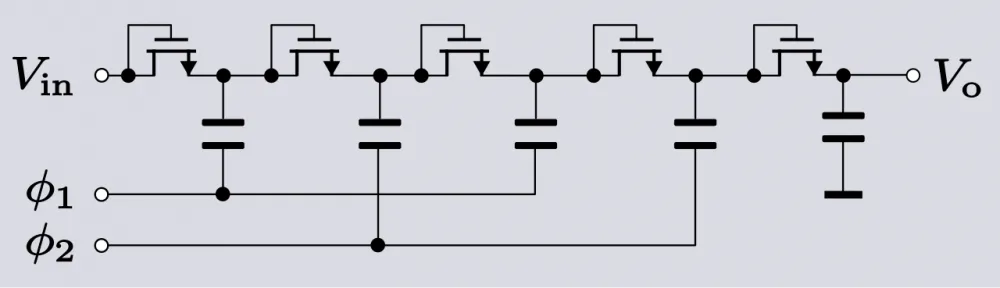
And maybe there is also a version on field transistors:
Finally, it might be useful: here is quite a complete online calculator for calculating multipliers.


Write comment