- DIY
- A
Let's light up an LED on STM32
There are tons of articles on the internet about how to blink an LED on esp8266. We propose to consider the same task, but on an alternative microcontroller - stm32.
Here is a small guide that describes how to light an LED using the STM32 microcontroller by configuring the GPIO pins. In the post, we will cover the basics of microcontroller registers and how to manipulate them directly. You will also find a step-by-step guide on writing code in assembly and C to control the LED.
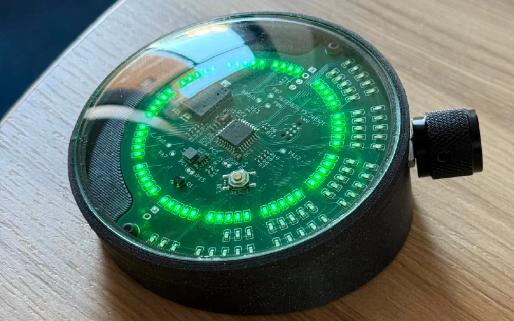
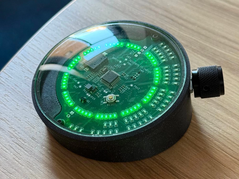
I worked on a driver for an array of 110 LEDs Charlieplexing with a countdown timer. The microcontroller used was STM32L010K4. It is a robust chip with ultra-low power consumption of 32 MHz, 16 KB of flash memory, and a colossal 2 KB of RAM.
I chose it mainly because it was the first in the vast STM32 microcontroller lineup. At that time, I thought that a chip with the fewest peripherals would be easier for me to learn. I designed the LEDs to be arranged in a circle and two arcs. The inner circle represents minutes, the middle arc - hours, and the outer - days:
In hindsight, I think I could have added an LED driver chip (for example, IS31FL3746A ) and saved myself a lot of trouble, but at that time one microcontroller seemed like a simpler solution. And now, having laid out the PCB (first manually on a breadboard, with more than 300 soldered connections, but that's a whole different story) and programmed a working driver, I realized that a separate chip for this purpose was not needed. In general, I am glad that I chose this solution for the first time.
LED Control
In this scenario, the LED is turned on by toggling a bit in a very specific memory cell. This is the bit that corresponds to one of the general-purpose input/output (GPIO) pins of the microcontroller. The two pins to which my first LED is connected are marked in the figure below. In my case, these were pins 7 and 14, in the datasheet they are designated as pins PA1 and PB0 respectively; which in turn means that they are in the GPIOA and GPIOB pin groups respectively. All this will allow us to find their address.
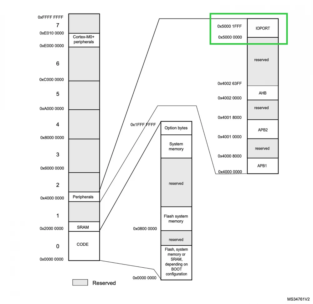
In the reference manual that comes with the microcontroller (page 40 of 784), there is a memory map showing that the controller's input/output ports (IOPORTS) are somewhere between 0x50000000 and 0x50001FFF.
And on the page below we can see that GPIOA starts at 0x5000 0000, and GPIOB starts at 0x5000 0400:
To connect an LED with the anode (+) connected to PB0 (GPIOB / pin 14), and the cathode (-) connected to PA1 (GPIOA / pin 7), we need to ensure that PB0 sends voltage (in my case 3.3V), and PA1 acts as ground. First, we set the mode of these pins to "general-purpose output mode" (1), and then toggle the bit corresponding to pin 14 in the GPIOB bit set/reset register (BSRR) (2). I will explain how this works later, but in short, these three steps are as follows:
1. 0x50000000 ← 0xEBFFFCF7
0x50000400 ← 0xFFFFFFFD
2. 0x50000418 ← 1
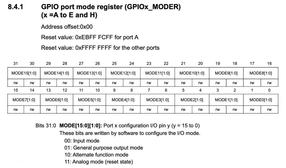
The first question you may have is: Where did 0xEBFFFCF7 (E:1110 B:1011 F:1111 F:1111 F:1111 C:1100 F:1111 7:0111), 0xFFFFFFFD (F:1111 F:1111 F:1111 F:1111 F:1111 F:1111 D:1101) and 1 come from? To answer this question, below is another fragment from the reference manual. It shows the bits that need to be set to configure the mode of GPIOA and GPIOB:
Let's first deal with 0xFFFFFFFD (the value of GPIOB_MODER). F in hexadecimal format, of course, will be 1111, and D is 1101, so 0xFFFFFFFD (F:1111 F:1111 F:1111 F:1111 F:1111 F:1111 F:1111 D:1101) is:
You see, all the pins, except for the 0th, are set to "11: Analog mode (reset state)", and pin 0 of GPIOB is set to "01: General purpose output mode".
0xEBFFFCF7 (the value of GPIOA_MODER), on the other hand, uses the same idea, only instead of fully analog mode, GPIOA starts in another reset state. Look at Figure 8.4.1 above, note that under the bolded heading it says: "Reset value: 0xEBFF FCFF for port A", because some pins are set to analog mode (14 and 13) and input mode (4) by default to enable programming and debugging of the microcontroller on certain pins. And we set pin 1 to "general purpose output" mode. So, 0xEBFFFCF7 (E:1110 B:1011 F:1111 F:1111 F:1111 C:1100 F:1111 7:0111):
The ability to simultaneously configure the modes of sixteen pins, in my opinion, is quite good, but at first it is not easy to understand.
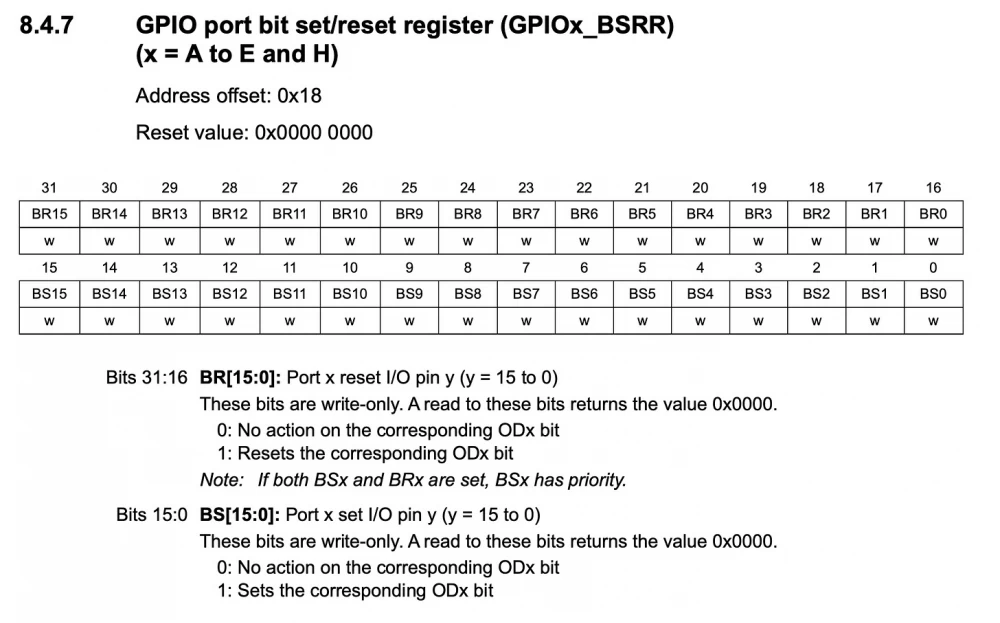
Finally, 1 (in 0x50000418 ← 1) is set in the bit set/reset register (BSRR) to send voltage to pin 0 of GPIOB:
Note the "Address offset: 0x18" at the top. Knowing that GPIOB is at address 0x50000 400 + 0x 18, we get that the BSRR for GPIOB is 0x50000418. So, to "set" the 0th bit to 1, we need to write 1 to memory at that address.
Here is the entire assembly sequence:
ldr r0, =0x50000000    // load the GPIOA address into register r0

ldr r1, =0xEBFFFCF7    // load the mode for GPIOA into register r1

str r1, [r0, #0x00]    // write value of r1 into address at r0

ldr r0, =0x50000400    // same as above but for GPIOB

ldr r1, =0xFFFFFFFD

str r1, [r0, #0x00]

ldr r1, =1             // load 1, which is pin 0 in PB0, into r1

str r1, [r0, #0x18]    // write that 1 into GPIOB with BSRR offset of 18

And in C:

*(volatile uint32_t *)(0x50000000) = 0xEBFFFCF7;

*(volatile uint32_t *)(0x50000400) = 0xFFFFFFFD;

*(volatile uint32_t *)(0x50000418) = 1;
But most likely, you will want to use CMSIS (Cortex Microcontroller Software Interface Standard) on top, which will make the code much more readable:
#include "stm32l010xb.h"

void turnOnLED() {

  GPIOA->MODER = 0xEBFFFCF7;

  GPIOB->MODER = 0xFFFFFFFD;

  GPIOB->BSRR = 1;

}
And to make our lives easier (and avoid calculating this hexadecimal value ourselves), STM supports a library called HAL (Hardware Abstraction Layer). Here's what it looks like:
#include "stm32l0xx_hal.h"

void turnOnLED() {

  GPIO_InitTypeDef GPIO_InitStruct = {0};

  GPIO_InitStruct.Pin = GPIO_PIN_0;

  GPIO_InitStruct.Mode = GPIO_MODE_OUTPUT_PP;

  HAL_GPIO_Init(GPIOB, &GPIO_InitStruct);

  GPIO_InitStruct.Pin = GPIO_PIN_1;

  HAL_GPIO_Init(GPIOA, &GPIO_InitStruct);

  HAL_GPIO_WritePin(GPIOB, GPIO_PIN_0, GPIO_PIN_SET);

}
For completeness, I will add that you will have to do a little more work before the above code works, namely configure and enable the clock generators that control GPIOA/B; but this part is done either by the code generator/bootloader tool supported by STM called STM32CubeMX (I prefer to use it with VSCode), or their IDE STM32CubeIDE.
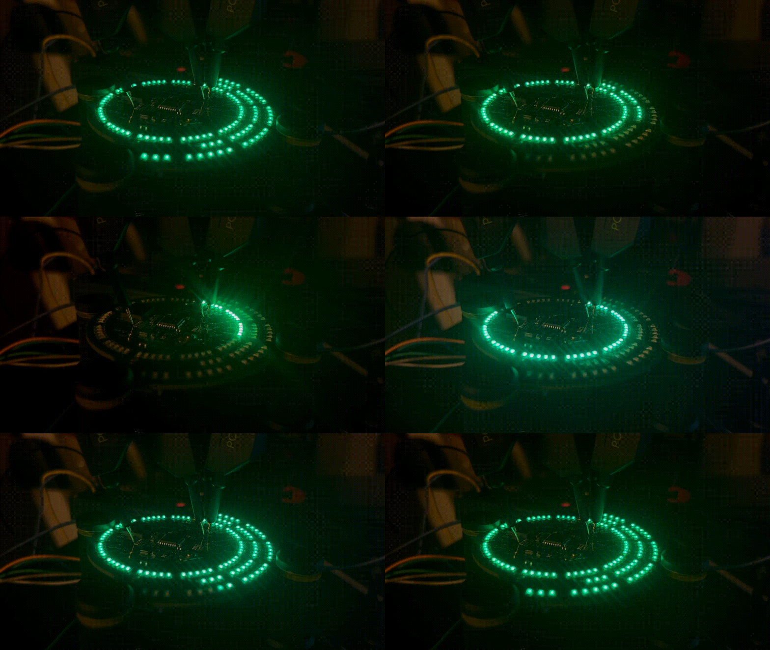
That's it: we set three values in three very specific sections of memory, and this sends 3.3V to one pin, while the other acts as ground. It turned out something like this:
Thank you for your attention!








Write comment