- DIY
- A
Warm Lamp Multivibrator
Interest in tube technology arises either from audiophilia, or when trying to restore a grandfather's receiver - or simply out of curiosity about retro electronics.
Teaching a basic electronics course at a local school, I inevitably encounter questions on this topic - and at some point, I decided to make such an educational craft - in order to better understand it myself. After all, in our age of controllers and digital circuitry, not many people are skilled in analog technology - and even fewer in tube technology.
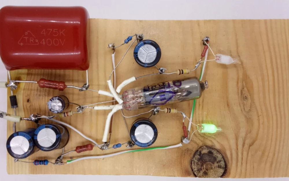
So here is a multivibrator on a double triode 6N2P and neon lamps (well, it's not nice to put LEDs in tube technology) - with transformerless power supply. Now I'll quickly explain what's what here :)
Let's make a reservation right away - due to the nonlinearity with "negative differential resistance" on neon lamps, you can make a blinking multivibrator by adding only a capacitor and a couple of resistors - but on the one hand, such a circuit has some limitations - on the other hand, this is not our goal :)
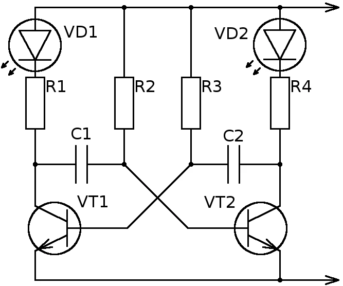
Multivibrator - a type of generator - a circuit with two states that constantly switch between each other. Invented about 100 years ago, it is found in all sorts of books in the form of a recognizable symmetrical circuit on a pair of transistors. My task is quite simple - to replace the transistors with tubes, taking into account their characteristics. And also somehow power this thing.
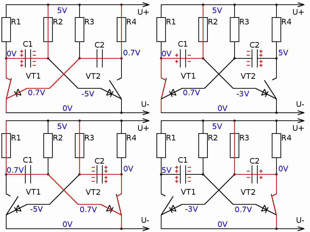
Its "on fingers" operation is that when one of the transistors is open (and the corresponding LED is on) - it locks the transistor of the second half. But this is done through a capacitor, the charge on which slowly changes, so at some point the second half opens and locks the first. Here is an animated picture, with transistors represented as keys:
And now - Lamps!
More precisely, one lamp - a double triode. As the name implies, it has two amplifying elements similar to transistors. However, there are significant differences with transistors (besides the high anode voltage):
current flows into the base of the transistor to open it - and the triode grid is controlled by voltage (it can be considered to have infinite resistance and nothing flows there)
the base of the transistor in the working (open) state should have a potential slightly higher than the emitter - and the lamp, on the contrary, is open by default - a small voltage below the emitter voltage must be applied to the grid to stop the electron flow.
With these theoretical ideas, I fiddled a bit and started designing a layout - for authenticity, with "stud" mounting - in the role of which small nails were used. I was lucky - my ideas turned out to be correct and the circuit worked. Here is what it looks like in full.
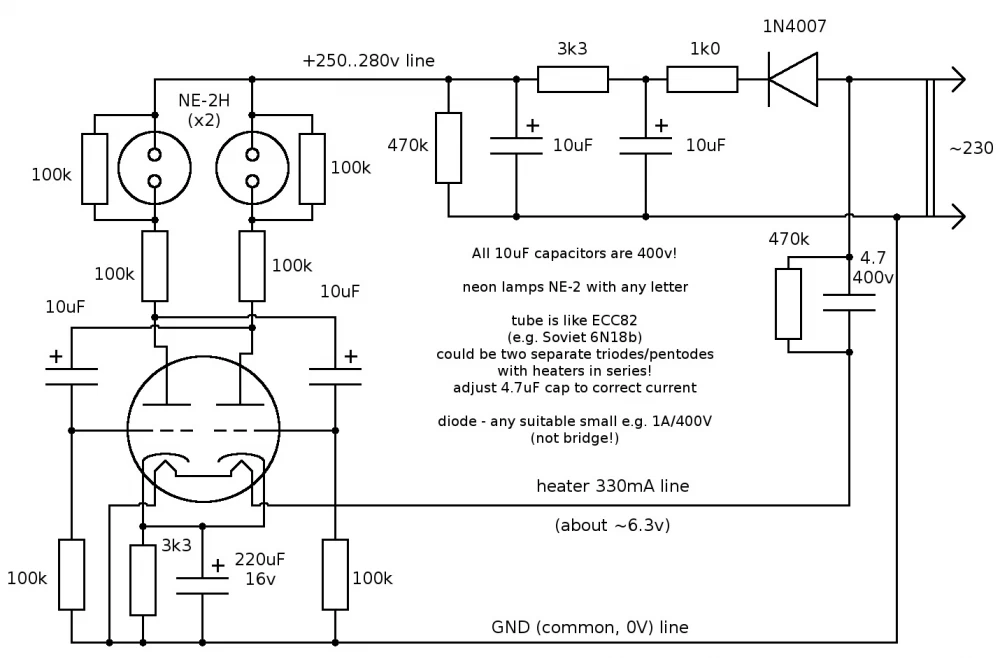
Sorry for the captions in English - I originally showed this to acquaintances on a foreign forum - but I drew the elements in our way :)
The multivibrator itself is at the bottom left, around the double triode resembling an intricate "smiley" - as we can see, the main change compared to the transistor circuit is that the resistors on the control electrodes are pulled down (to the negative) rather than up - to lock the triodes rather than open them.
To ensure that the minimum voltage on the grids is slightly below the cathode voltage, the cathodes need to be "propped up" with resistors - then the current passing through the tube will create a small voltage drop across them, "raising" the cathodes "above" the potential of the negative wire to which the grids are connected. As you can see, there is one such "propping" resistor for both cathodes - and it is paralleled with a capacitor to reduce the influence of changes in the anode current during the operation of the multivibrator on the level of this prop.
Above the triode is the part with the neon lamps. Here everything is clear, typical limiting resistors - for neon lamps they have a higher resistance than for LEDs - but the principle is the same. A neon lamp in working condition has a stable voltage drop of about 60V - and all the excess must be burned off on the resistor, otherwise it will "boom" as Piglet would say :)
Why I added two resistors in parallel with the neon lamps - I have already forgotten - I think without them the circuit does not start - we need the potential of the anodes to be close to that on the positive wire when both triodes are closed - and here the neon lamps lose 90V in the closed state. If instead of neon lamps there are LEDs or miniature incandescent lamps - these two resistors can definitely be discarded.
Power Supply
This part is no less interesting. Usually, tube equipment is powered through a hefty transformer - which has a pair of secondary windings - low-voltage and powerful for heating - as well as relatively low-current high-voltage - for anode circuits. Such a transformer weighs a kilogram or more - and in a small circuit it looks unattractive (not to mention that it is a valuable thing, not cheap).
Therefore, we will power it directly. With the anode circuit, everything is simple - we took a diode (why not a bridge? I'll tell you now) - and added a two-stage RC filter - and here you have about 300 volts at the output. Do not forget the "discharge" resistors for the capacitors - it will be bad if you get a shock from an already turned off circuit.
With the heating circuit, it is more complicated - it has a relatively large current (hundreds of milliamps for this lamp) - but low voltage (about 6 volts). You could put a fat resistor that will "eat" all the extra 200 volts with a tail. It is not difficult to estimate that the power of such a resistor will be something between a soldering iron and a boiler :)
Therefore, instead of a resistor - a capacitor. It creates "reactive" resistance to alternating current. The capacitance can be calculated using the formula for the reactive resistance of a capacitor (it depends on the frequency) based on the desired current, according to Ohm's law (we simply ignore the voltage drop on the filament itself). In general, it is very convenient - including for various battery chargers and so on - only it is important that the capacitor should be film (not electrolytic) and therefore quite large (the larger the current needed, the larger it is). And it also needs a discharge resistor.
And here lies another nuance. The filament circuit with a capacitor as a resistor is connected directly between the AC voltage wires. The rectifier circuit for the anode voltage is also between them. At the same time, we need the negative anode voltage to be on the same wire to which the filament is connected!
If we inserted the capacitor not to the right but to the left of the filament circuit (according to the diagram) - or if we used a bridge rectifier circuit - the filament and the negative circuit (with the cathode) would not be directly connected - and a potential difference of hundreds of volts would arise between them in each period of the mains voltage. Because of this, the filament itself would become an additional anode :) Of course, it will not work exactly like the main anode (due to heating and the lack of coating on the inside of the cathode - but still, depending on the circuit, it can greatly spoil the life. In a multivibrator, this might be less critical - but in some amplifier - quite.
Demo
That's basically it
If you decide to repeat this craft, of course, do not forget about safety measures (we all know how easy it is to miss something in a hurry) - when turning on, work with only one hand, if possible in a glove. Use tools with insulating handles. Do not poke around in the circuit while it is on.



Write comment