- DIY
- A
Model of an Alternating Current Generator Made from Available Materials
This article details the process of creating and assembling a model of an alternating current generator with pictures.
In this article, I will explain how to make a model of an alternating current generator from available materials. Relevance of the work: I consider my work relevant as it teaches how to apply the laws of physics in practice. The significance and practical value of the results obtained lie in the fact that the generator model can be used in physics lessons when studying the phenomena of electromagnetic induction.
To make the generator, you will need: Materials: thick plywood, galvanized iron, a bolt, screws, neodymium magnets, nuts, coils made of copper wire, glue. Tools: pliers, metal saw, screwdriver, jigsaw, pencil, metal scissors.
Making the model
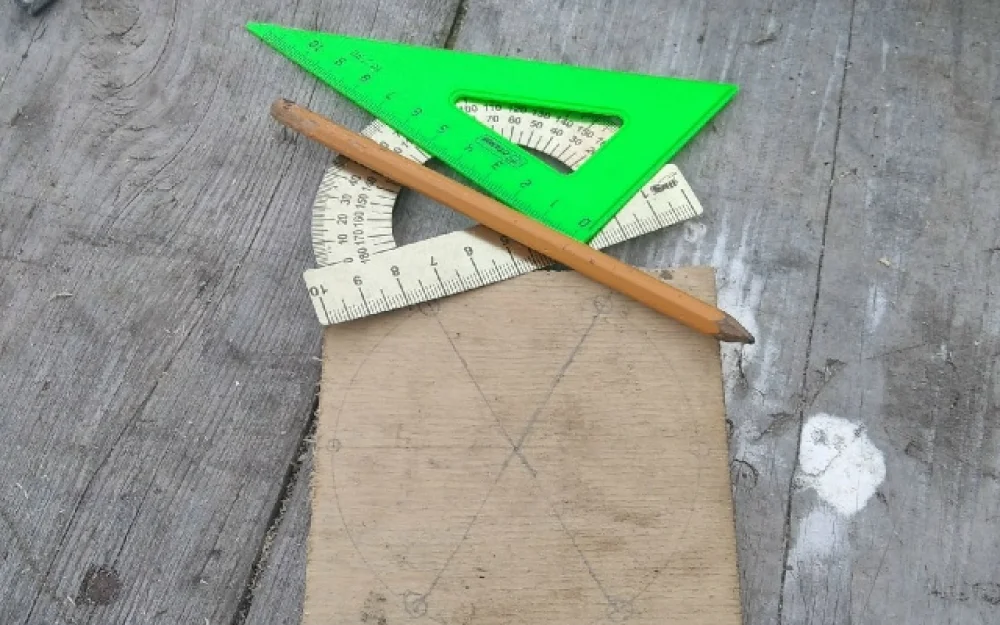
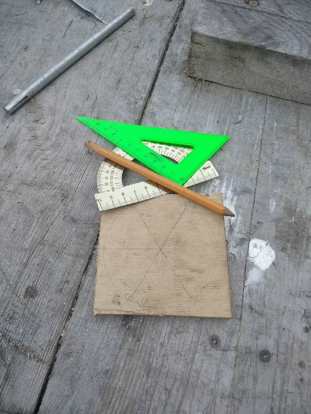
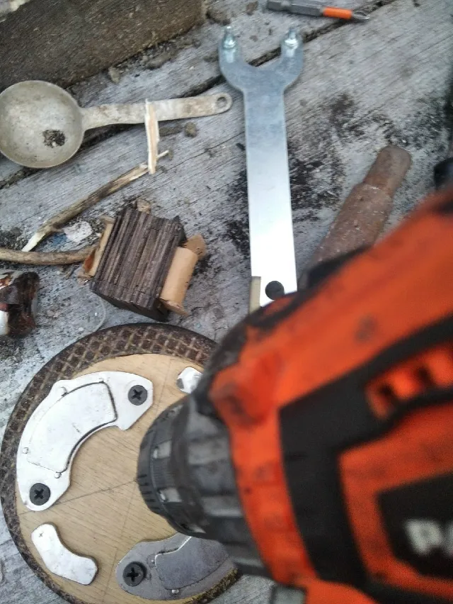
First, I cut the base out of plywood using a hacksaw,
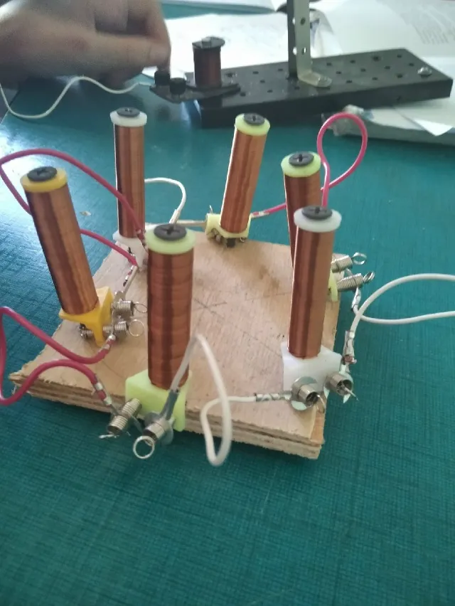
and placed 6 coils around it using a screwdriver and self-tapping screws. Next, I connected the coils in series and brought out two ends.
Then I drilled an 8 mm hole in the center. I cut a small piece of galvanized iron and screwed it to the hole. This way, I made a bottom for the rotor axis. Then I cut a circle out of plywood with a diameter of 10 cm and attached two neodymium magnets taken from old hard drives with self-tapping screws, and glued two more magnets with super glue so that the polarity alternated.
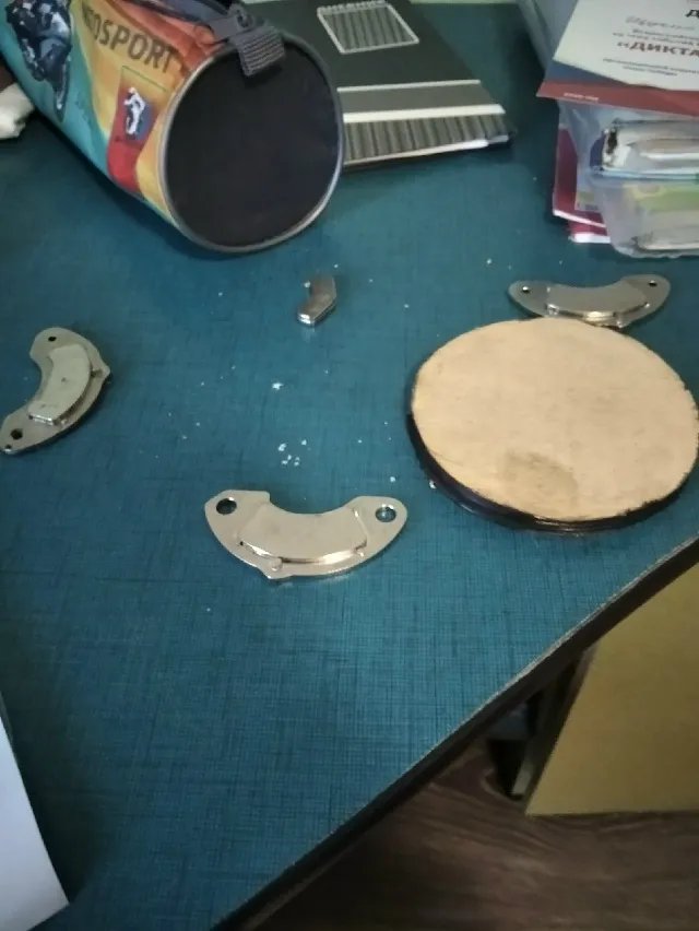
Then I drilled a hole in it with a screwdriver. A rotor disc was formed.
Next, I cut two strips from galvanized iron, each 35 cm long, using metal scissors, and bent them with pliers at the appropriate places. In the center, I drilled an eight-millimeter hole. The crosspiece protects the rotor from a large number of revolutions and ensures the integrity of the structure.
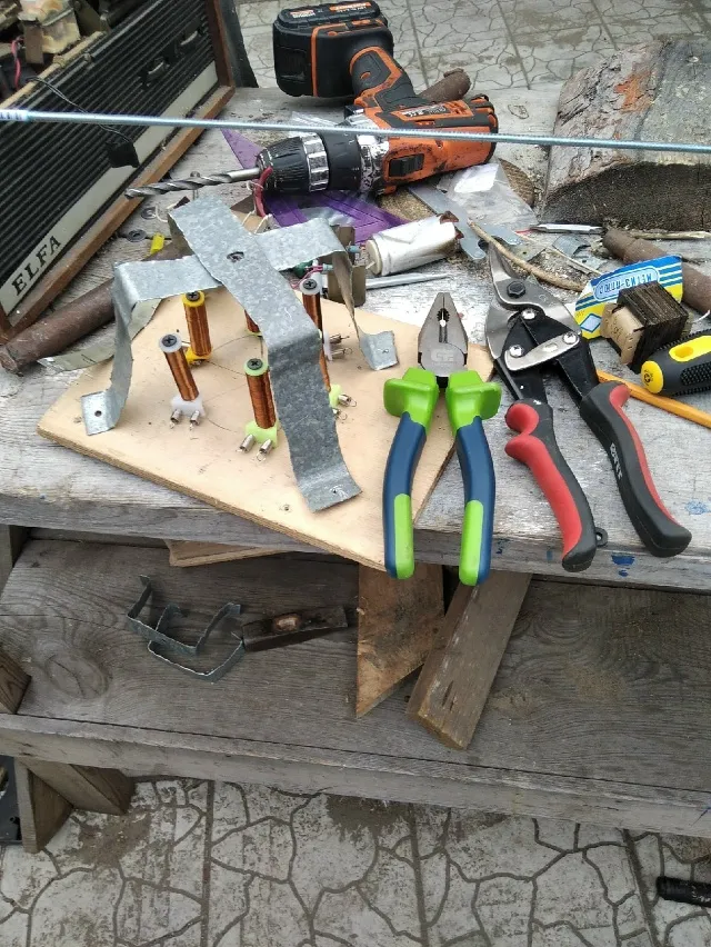
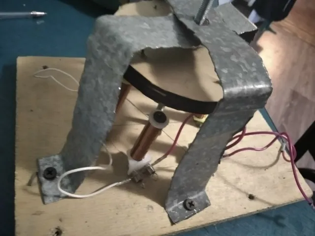
As an axis, I chose a piece of rod about 16.5 cm long and 6 mm in diameter, cut with a metal saw. Then I assembled the generator: I placed the rotor disc on the axis and secured it with nuts, washers, and glue, installed the axis perpendicular to the base, and attached the crosspiece to the base with self-tapping screws after drilling the appropriate holes in it.
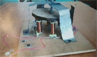
Testing the generator in practice
I check the operation of the generator by connecting a LED to it. The rotor axis is driven in a rotational motion by a screwdriver (maximum speed - 1250 RPM), the LED lamp lights up.
Direct measurement with a multimeter shows I=42mA and U=5V.
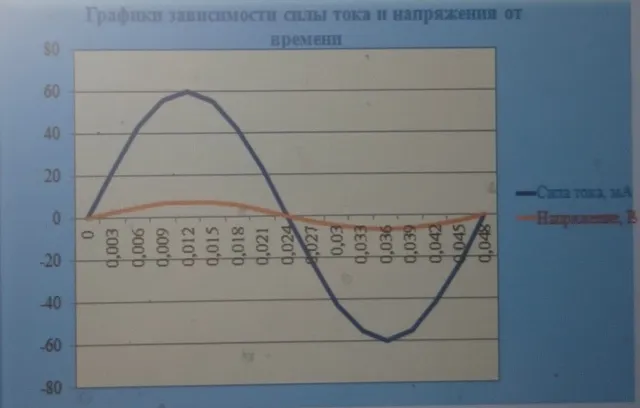
These are the operating (average) values of current and voltage. The maximum current value is 60 mA, and the maximum voltage value is 7 V. Since the screwdriver has P=24 W, the efficiency is about 3%. Moreover, this current is alternating; to confirm this, I used a voltage sensor. Instead of the LED, I connected a sensor to the generator model. Using the voltage sensor and LabQuest device, we obtained a graph of the voltage dependence on time.
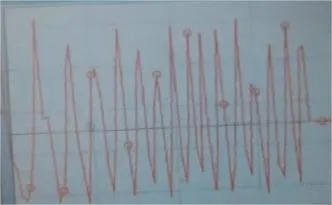
After analyzing the graph, I concluded that the current changes not only in magnitude but also in direction. The graph shows slight changes in the amplitude of the voltage and the period of oscillation. This can be explained by the fact that the number of revolutions of the screwdriver varied depending on the pressure applied. The operation of the created AC generator model can be viewed in the video linked here.
The entire structure is designed to demonstrate the generation of alternating current through the movement of permanent magnets relative to coils. When creating the generator model, I relied on the experience of generating induced current during motion. I improved my skills in working with various tools (from pliers to a screwdriver), as well as my creative skills.
The model can be improved: add a homemade gearbox with a high transmission ratio so that it can be rotated manually.


Write comment