- DIY
- A
Kiisu — a board compatible with Flipper Zero
It all started when I forgot the key to the gate to the yard and remembered my last year's idea to make something similar to Flipper, but more compact, so that I could always carry it with me. Last year, I didn't get around to implementing it, but this year I did.
Join me under the cut to see what happened and discuss how to make it better :)
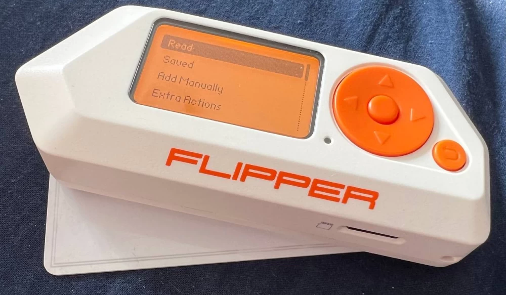
Flipper Zero
Flipper Zero is a portable multifunctional Tamagotchi-like device designed to interact with access control systems and other systems that use a radio channel for communication. The device can read, copy, and emulate RFID and NFC tags, radio remotes, iButton and digital access keys, and also has a GPIO interface. (c) Wikipedia
However, I think everyone already knows this. The Flipper team did an amazing job creating a very high-quality, interesting, and well-thought-out device, which is known to almost everyone who is even slightly interested.
Widespread recognition also means an ecosystem. In addition to the device itself, there are several projects of modified firmware, a large number of third-party applications (you can see them here - Flipper Lab), and dozens of expansion modules, both from the team and third parties.
I also have a Flipper. It's great, but as I wrote a year ago, it's too big to carry with me all the time. And you never know when you'll forget your keys! So what to do? That's right. Make your own :)
First option
So, let's go. First, let's formalize the requirements:
The same functionality: SubGHz, NFC, RFID, IR, iButton, GPIO. It's simple here - we implement these nodes in much the same way as in Flipper, the schematics of which are available on the website.
Maximum compactness. There are two options here - either abandon the autonomous mode altogether, and with it the screen and battery, or still maintain autonomy. We will choose the latter, using a compact and affordable screen on the SSD1306, and instead of a large battery, we will use the CR2032 (or the rechargeable version - LIR2032). Yes, the energy reserve is now much smaller, so we will have to sacrifice the tamagotchi mode - we will completely turn off the power after a minute of inactivity.
Compatibility with Flipper firmware in binary form. Of course, the firmware is open and nothing prevents making small changes, but this still reduces convenience. And in our device, the OLED screen, which is initialized differently and will not work "just like that". What to do? We will add another STM32 between the screen and the heart of the device - STM32WB55! And at the same time, we will ask it to emulate responses from the PMIC and Fuel Gauge and manage power.
Minimal cost and ease of production. We will simplify the device a bit and choose components that are available at JLCPCB right away.
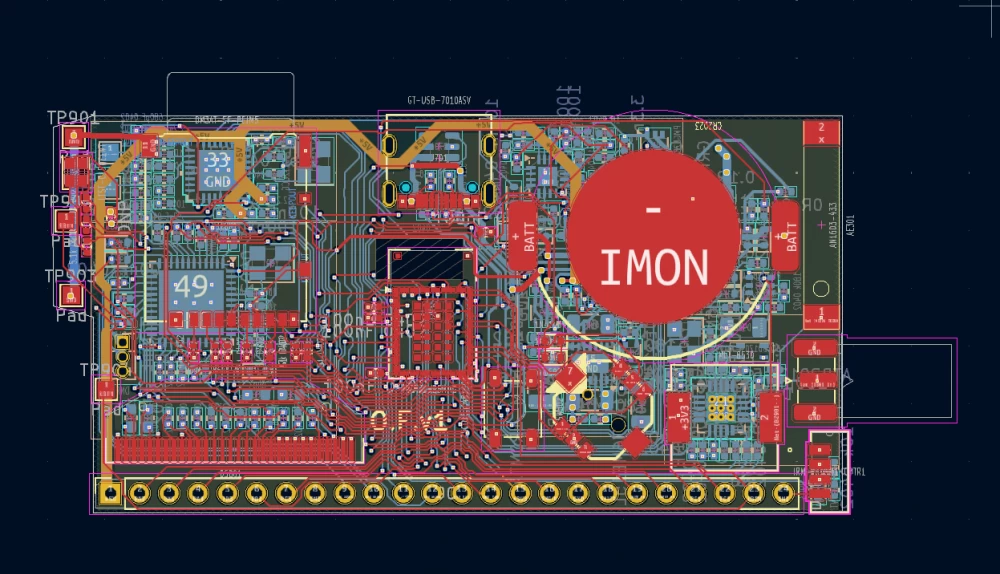
For the development of the board, I decided to try KiCad. For a long time, it seemed to me that it was too raw and even inexpensive EDAs like DeepTrace were obviously better, not to mention Altium, but one friend actively advertised KiCad, so why not?
The board is four-layered, two layers are dedicated to GND and VCC, and the two outer layers are signal layers. Many still think that multilayer boards are complicated. In fact, even 4 layers significantly simplify the work and almost eliminate the difficulties with proper grounding and power routing. The manufacturing time and cost for the Chinese increase insignificantly - three days instead of one.
What to do while the boards are not here?
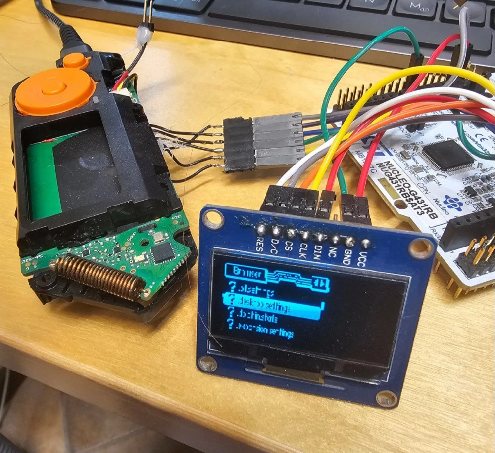
Let's write the firmware for the second MCU, initializing the display.
It's not difficult - we receive data for the display via one SPI, filter everything except data packets, initialize the display ourselves, and send the image data as is (in this case, their format matches).
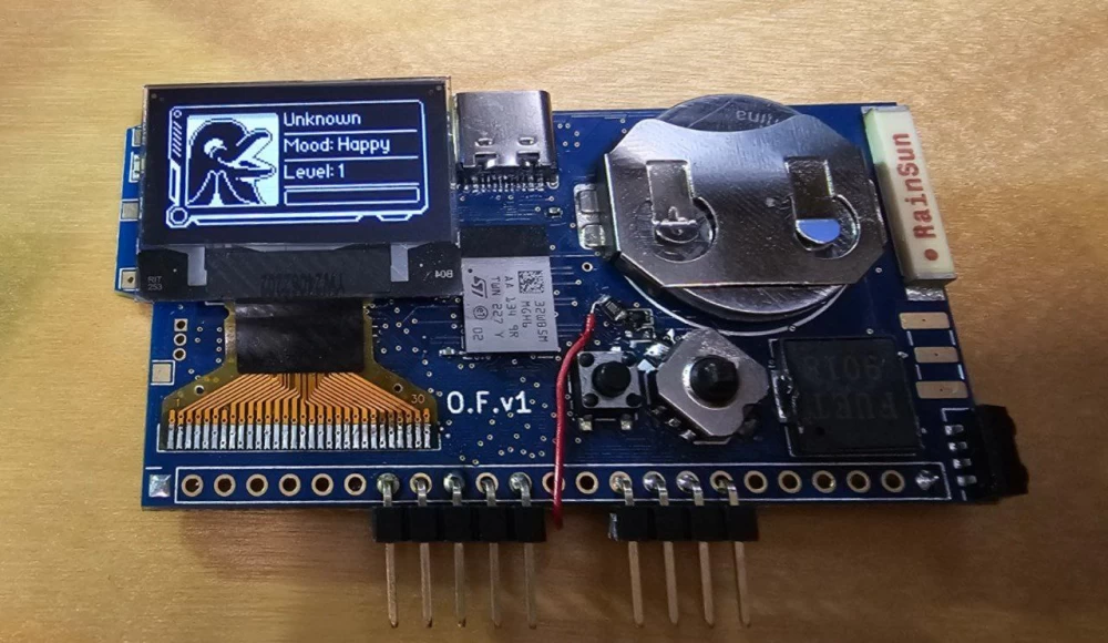
By the way, in the picture on the left, you can see what happens if you don't process the data fast enough :)
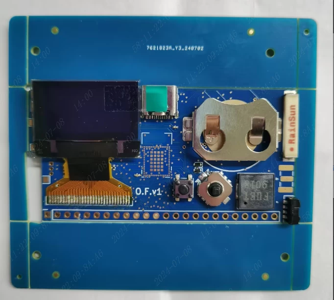
Two weeks pass, and the boards are on my table. But I saw them earlier - you can ask the Chinese to photograph the assembled boards before shipping. Like this:
Instead of the STM32WB55RGV, the STM32WB5MMG module was used - it's the same, only with integrated antenna, quartz crystals, and some other components. Great, I thought, the board will be simpler!
As it turned out, the solution was so-so :) The chips have one-time programmable memory, the place where the unique name of the Flipper, its version, region, and other data are stored. For individual MCUs, this area is empty. And for MMG modules, the first 8 bytes are occupied by antenna calibration data, and these are exactly the 8 bytes we need!
In the first version, of course, there were quite a few errors. MISO and MOSI are swapped on the NFC chip. Part of the pins of the op-amp, on which the RFID is assembled, are swapped. The central button is shorted to ground, but it should be to VCC.
But the version is test, after all, to identify all this, so it turns out even faster than trying to check everything very, very carefully before ordering.
And fortunately, we have Jedi Oleg in our team, capable of re-routing tracks with jumpers at a distance of 0.1 mm not only without a microscope, but even without a lamp and a magnifying glass! For example, it's difficult for me even with a microscope :) After all, I'm a cat, I have little paws!
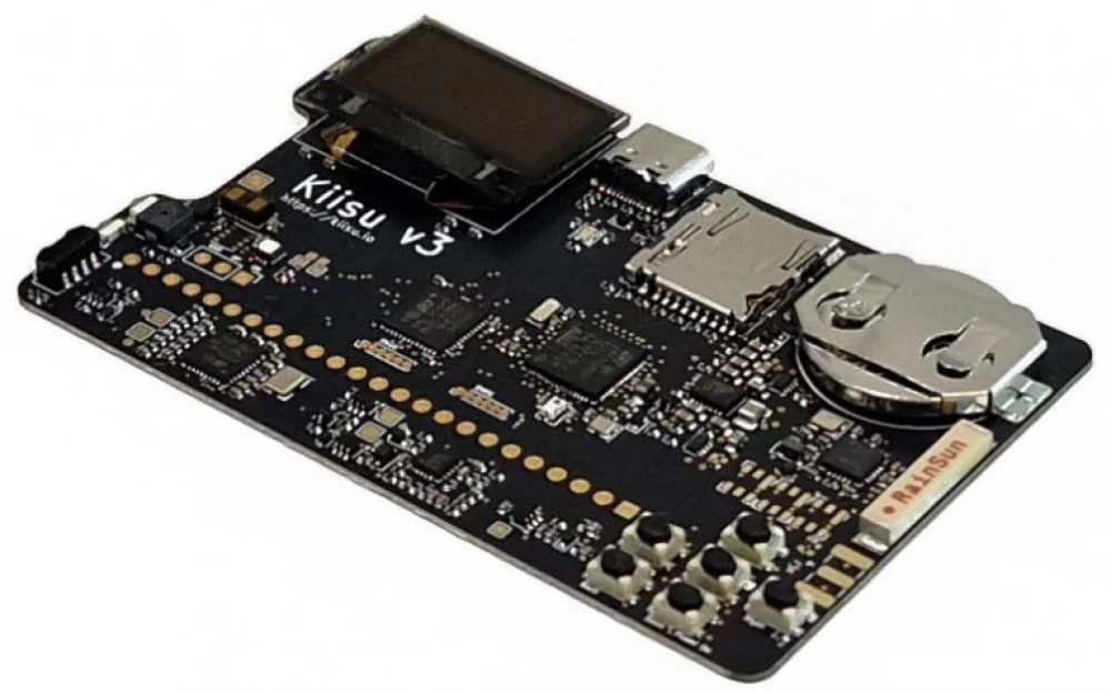
Kiisu
Why Kiisu? We had to name it somehow without using the word Flipper, because we are not related to Flipper Devices Inc :)
Kiisu is a kitten or cat in Estonian. It seems quite suitable to me - we have a cute little device, but capable of a lot.
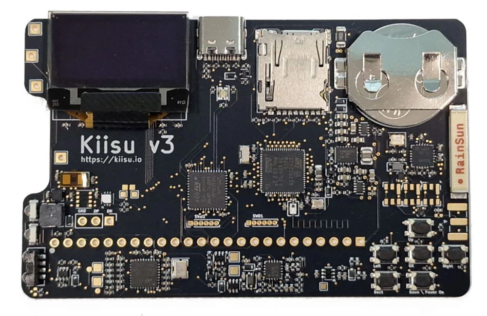
In this version, it was decided not only to fix errors, but also to redesign the form factor to the size of a credit card. Yes, the dimensions have become larger, but this allowed all components to be moved to one side, reducing the thickness to four millimeters (this is about 5 plastic cards stacked together). This means that Kiisu can now simply be put in a wallet and always taken with you!
What else has changed?
Of course, errors have been fixed.
Instead of the STM32WB5MMG module, now the regular STM32WB55RGV. Yes, the user will be able to write anything they like to the OTP memory.
A humidity and temperature sensor, an accelerometer and compass LSM303, the ability to install a ToF rangefinder VL53xxx and an air quality sensor BME680 have been added.
A light sensor (actually just a phototransistor) has been added, along with the ability to check LED lamps and monitors for flickering.
What's next?
Within 1-2 months, we plan to start selling Kiisu to everyone. For now - in Europe, but we are also working on other options. The expected price is around 60 EUR, but this is not very accurate yet.
And of course, we plan to continue making improvements, and promptly. The form factor will remain the same and will not change anymore, but we do not need to release a million units at once - and this allows us to act much more flexibly.
Write in the comments what you would like to add to make Kiisu better, and maybe it will appear in the fourth version!



Write comment