- DIY
- A
Electromotive force and electric current, using the example of sinusoidal current. Visual explanation
Let's try to explain the features of the appearance of variable EMF and electric current. The article is written with an emphasis on simplicity and clarity, without unnecessary complication.
Let's create a simplified AC generator and try to determine at what point the electromotive force (EMF) will begin to appear and change over time in the stator winding of the generator.
We will determine and observe all changes using a digital oscilloscope.
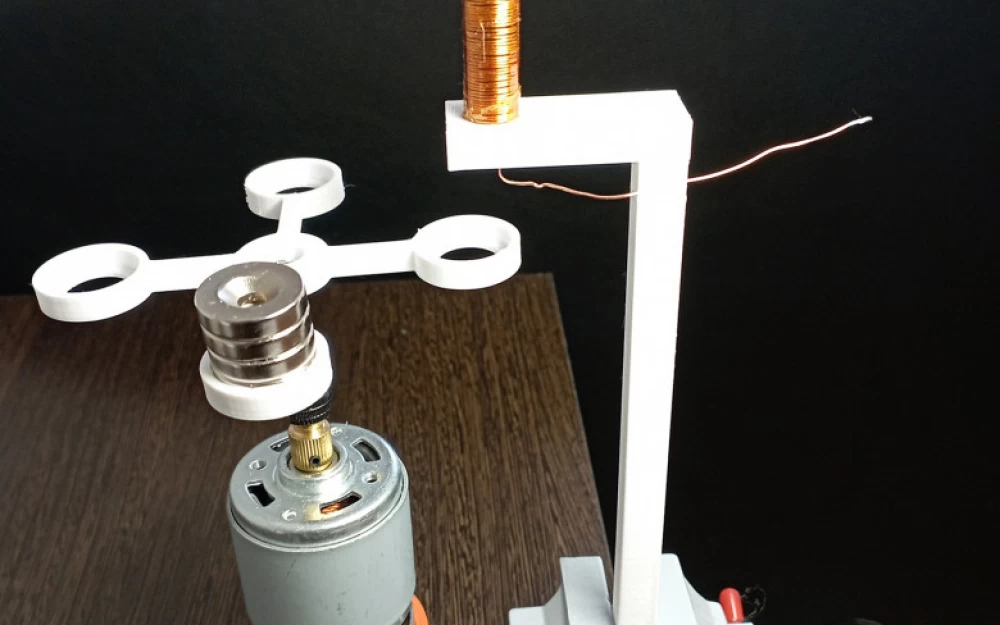
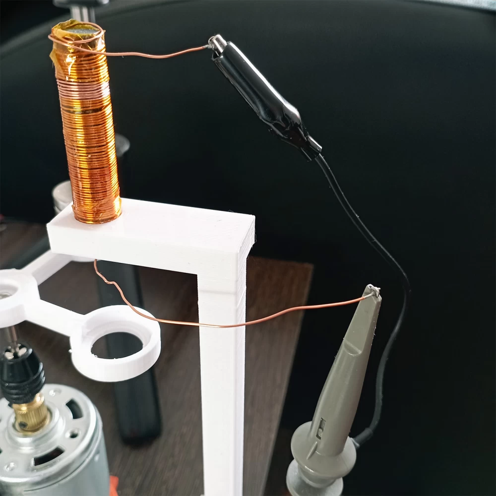
The generator is a motor with a platform on its shaft, on which there is a permanent magnet. In our experiment, 1 magnet (assembled from several magnets) will participate. When the platform rotates, this magnet will pass near the solenoid (inductance coil). An oscilloscope will be connected to the coil, which will display all changes on it (Fig.1).
Sine wave.
In the presence of an alternating magnetic field, that is, at the moment when the rotating magnet approaches and then moves away from the coil, an electromotive force appears in the coil, which is measured in volts. The coil also has a magnetic field. And if you close the circuit by connecting a load to the coil, an electric current will flow through the external circuit, which can be measured.
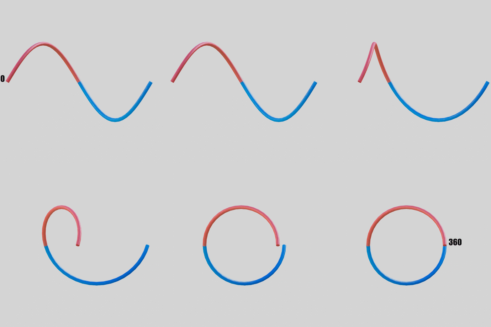
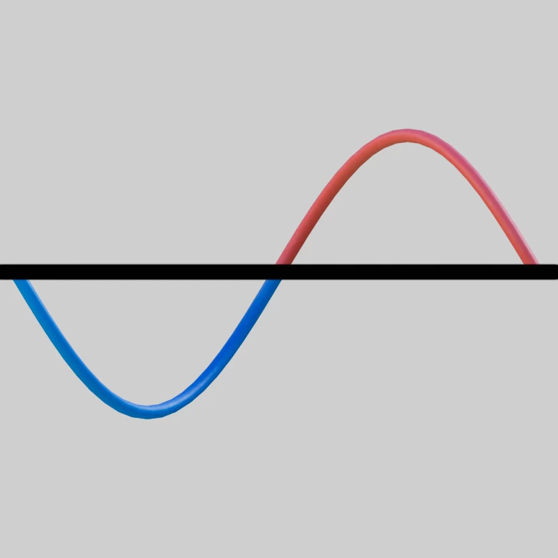
The way in which electric charges will move and how exactly the electric current will behave depends on the EMF, which is associated with the rotation of the magnet, which in turn gives an alternating magnetic field. In our case, the signal will be in the form of a sinusoidal wave. Let's depict a sine wave, but not in one plane, as is usually done, but let's depict it in 3D (Fig.2).
The animation shows a sine wave, one full period. The red color shows half a period (180 degrees), and the blue color shows the other half period (180 degrees). The full sine wave is 360 degrees. The red color indicates the direction of electric current flow in one direction, and the blue color in the other direction. The height of the wave is the amplitude. The greater the amplitude, the greater the magnitude of the electric current. The duration of the period depends on how fast the rotor with magnets rotates (in my case, a platform with a permanent magnet) or, in other words, on the speed of the magnetic field change near the coil. The speed of the magnet rotation near the coil also affects the amplitude, the height of the wave.
Generation of variable electromotive force and electric current.
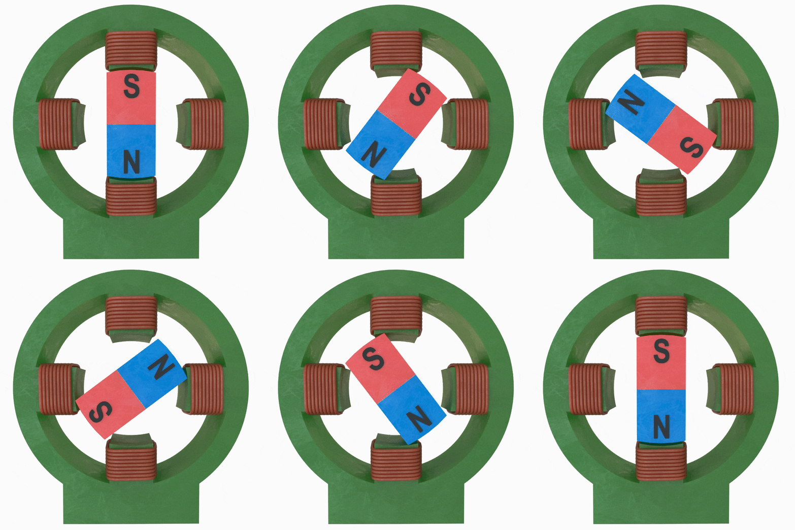
Based on the setup (Fig.1), we will conduct an experiment to detect EMF in the coil connected to the oscilloscope. The photo with the setup in (Fig.1) is similar to an AC generator, a simplified image of which is shown in (Fig.3). In this animation, the stator/magnetic circuit and the rotor are shown as a permanent magnet with two poles, north (N) and south (S). There are also windings on which EMF will appear under the influence of a variable magnetic field due to the rotation of the permanent magnet.
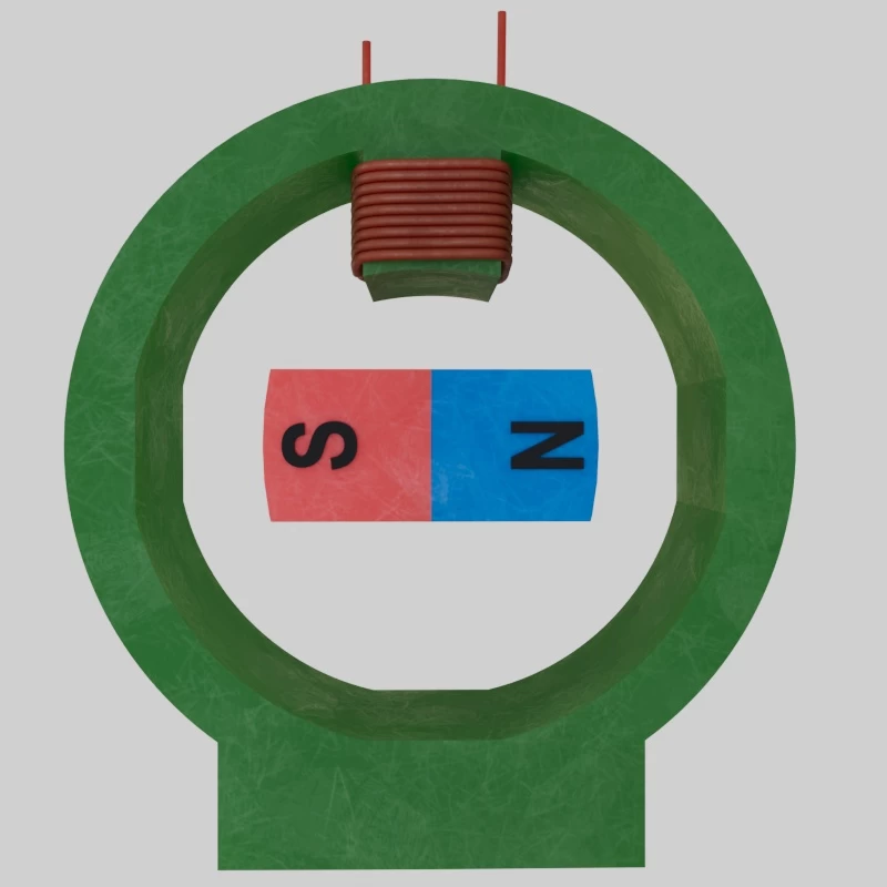
Since our experiment has only one winding, we will simplify (Fig.3) by removing the excess.
(Fig.4) shows a generator that will reflect all the changes in the real setup on which I will conduct the experiment. We see only one active winding. And the rotor is in the position where the experiment will begin. In the initial position, the magnetic poles are removed from the coil, and we will assume that in this position they do not affect the coil. The stator itself can be considered inactive or dielectric, for example, plastic. At the same time, we rely on the real experiment (Fig.1), in which the magnet is also removed from the coil in the initial position.
The purpose of the experiment is not to turn on the engine, thereby causing the rotor to rotate and observing the sinusoidal signal on the oscilloscope.
The purpose of the experiment is to understand at what point an electromotive force appears on the coil and how it changes over time, as well as what its polarity is and what magnetic poles appear on the coil at any given time. We will observe the initial moment of the appearance of the sinusoid. For this, I will not start the engine, but will rotate the rotor with a permanent magnet by hand. The sensitivity of the oscilloscope is sufficient to detect the appearance of EMF on the coil even at such a low speed.
In this experiment, the magnet will interact with the coil only with the south pole. If you look at (fig.1), you can see the south (S) pole of the magnet.
Rotation of the rotor to a certain degree.
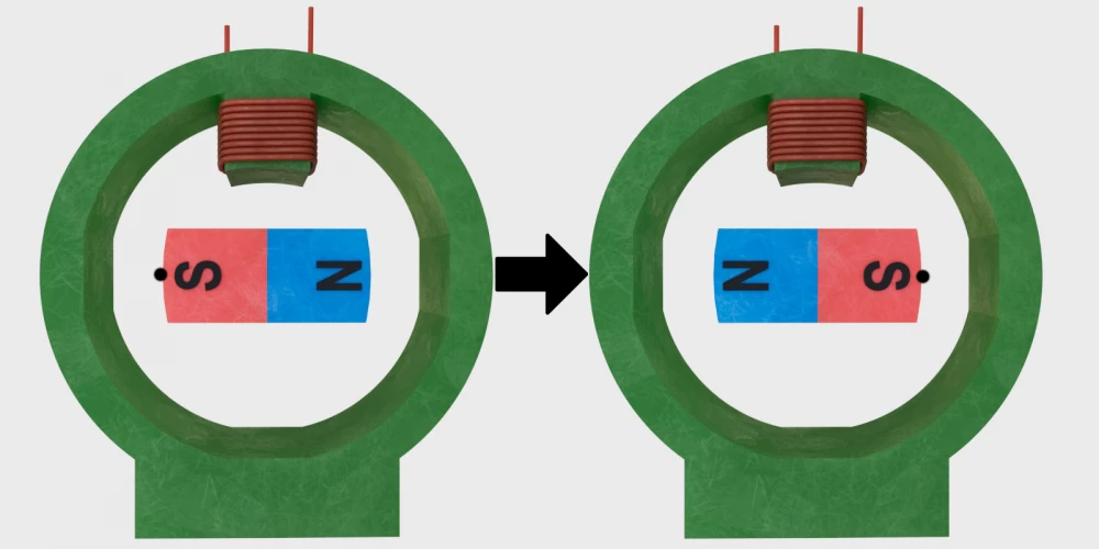
For the initial position, we take the position of the rotor as in (fig.4). The south pole of the magnet is on the left side, and the north pole is on the right. We will rotate the rotor-magnet clockwise.
First, let's clarify the obvious: if you turn the rotor-magnet clockwise by 360 degrees, the orientation of the magnet will return to its original position. If you turn the rotor-magnet by 180 degrees, the south pole of the magnet will be on the right side, and the north pole will be on the left. If you turn the rotor-magnet by 90 degrees, the south pole of the magnet will be in the center of the coil, at the top.
At this stage, we will rotate it half a turn, that is, 180 degrees, from the initial position.
We connect the oscilloscope probe: the signal one from the bottom of the coil, and the ground, which is the black crocodile clip, from the top of the coil (fig.5).
1. We will try to turn the platform with the magnet 180 degrees clockwise as quickly as possible (fig.6).
- Let's observe the changes on the oscilloscope screen (Fig.7). We see a sine wave, exactly one period, which lasted approximately the time we spent turning the magnet 180 degrees from the initial position. The part of the sine wave below the zero line indicates a negative polarity EMF. And the other part of the sine wave, which is above the zero line, indicates a positive polarity EMF.
(Since the magnet is rotated manually, the signal shape differs from a pure sine wave, but all examples will be shown using a pure sine wave.)
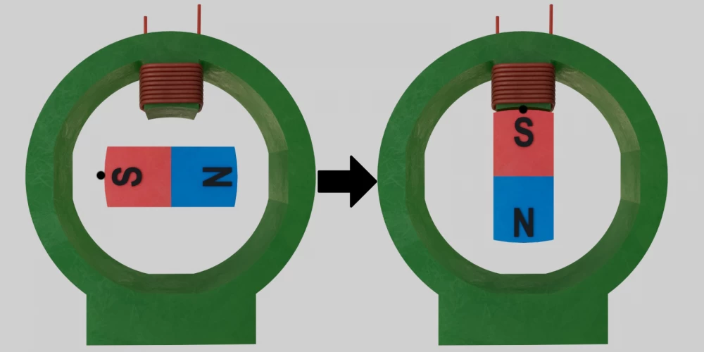
2. Now let's turn the platform with the magnet 90 degrees from the initial position. In this case, the magnet should be exactly in the center of the coil (Fig.8 a, b).
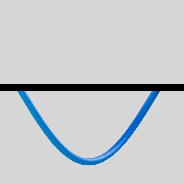
- Let's observe the changes on the coil, which will be shown by the oscilloscope (Fig.9). We can observe one half-wave of blue color, which is below the zero line. This means that if we close the circuit by connecting the bottom and top of the coil with a wire and connect a load to this circuit, the current in this case will flow in one direction, from plus to minus. The oscilloscope's signal wire indicates the minus, and it is at the bottom of the coil. This means that the plus will be at the top of the coil, which in turn means that the current will flow from top to bottom through the external circuit. Electric current always flows from plus to minus.
3. The next experiment. Let's take the initial position of the magnet as in (Fig.10a). That is, the magnet is in the center of the coil, with the south pole up. In the last experiment, it stopped in this position.
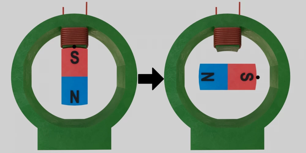
Quickly turn the magnet 90 degrees clockwise (Fig.10b).
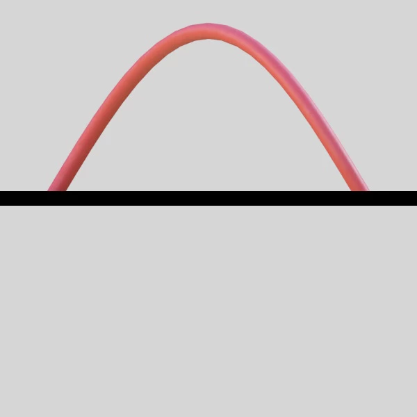
- Let's observe the changes shown by the oscilloscope. We can see a half-wave of red color, which is above the zero line (Fig.11). In this case, the EMF will have a positive polarity at the point where the oscilloscope signal wire is connected, relative to the crocodile wire and the top of the coil. This means that if we close the circuit by connecting the bottom and top of the coil with a wire, the electric current in this case will also flow in one direction, and also from plus to minus. The oscilloscope signal wire indicates the plus, and it is located at the bottom of the coil. This means that the minus will be at the top of the coil, which in turn means that the electric current will flow from bottom to top through the external circuit.
Conclusion.
- When the magnetic pole approaches the stationary coil, the EMF will indicate one polarity, and when the same magnetic pole moves away from the coil, the EMF will indicate the opposite polarity.
- The direction of magnet rotation does not change the picture. If we rotate the magnet in the opposite direction, nothing will change. The main thing is whether the magnetic field is approaching the coil or moving away from it, this will determine the polarity of the EMF, and therefore the direction of the electric current, in the end.
- If we conduct the same experiments, but with a different magnetic pole, namely the northern one, the conclusions made above will remain. But the polarity of the EMF will change to the opposite of what it was in the experiment with the rotating southern pole.
The appearance of the magnetic field at the stator, when the magnetic field of the rotor rotates.
It turned out that when a magnet approaches the coil with the south pole, the oscilloscope records a negative polarity at the bottom of the coil, which means that there will be a positive polarity at the top of the coil. This indicates the magnetic field with which poles the inductance coil will have. At the same time, if you change the direction of the coil winding, the polarity that the oscilloscope will show will change to the opposite. The magnetic field of the coil will remain the same, it will not change its poles. In this experiment, when a permanent magnet approaches the coil, in any direction of winding this coil, the south magnetic pole will always be at the bottom of the coil.
The following happens: when a permanent magnet approaches the inductance coil, we have an alternating magnetic field. The alternating magnetic field creates a vortex electric field in the space near the coil. When the coil appears in this electric field, it creates its own magnetic field, and current flows through the internal circuit. Since we already have a south pole from a permanent magnet at the bottom of the coil, the resulting magnetic field of the coil, with its south pole, will prevent the permanent magnet from approaching the coil.
When the permanent magnet moves away from the coil, the oscilloscope shows a positive polarity at the bottom of the coil, which means that there will be a negative polarity at the top of the coil. This allows you to determine the poles of the magnetic field of the coil induced by the electric field. In this case, the north pole will be at the bottom of the coil, and the south pole will be at the top. Since there is already a south pole of a permanent magnet at the bottom of the coil, the created north pole of the coil will prevent the permanent magnet from rotating, that is, from moving away from the coil at this moment in time.
It turns out that in AC generators with a rotating rotor, on which permanent or electromagnets are installed, a magnetic field appears on the stator windings of such a generator, which always counteracts the rotation of the rotor.
Supplement:
In general, the situation is as described above, but there is one additional point that I will describe separately.
As shown, when the rotor with a permanent magnet rotates, as one pole approaches the coil and then moves away from this pole, we get a sine wave on the oscilloscope screen, one period. At the same time, we get a variable EMF and an oscillation of the electric current, first in one direction, then in the other. Further, these oscillations can be repeated, as the rotor constantly rotates. But if we consider the option, for example, with the approach of the magnet to the coil and its subsequent rapid stop, then as shown, we will see only half of the sine wave, one half-wave. In general, the situation is as described. When one pole approaches, we have one half-wave, when the same magnetic pole moves away, we have another half-wave. But this is while the rotor with magnets is in motion. Since in our experiment there is a stop of the rotor/magnet, this stop means the absence of an alternating magnetic field. This means that there is no reason for the appearance of an eddy electric field, which in turn means that at the moment when the magnet stopped and we observed one half-wave on the oscilloscope, then after the magnet stops, a weaker half-wave of the opposite sign will appear. This is due to the fact that there are no dynamic forces acting on the coil after the magnet stops. After the alternating magnetic and electric fields disappear, the coil should return to its equilibrium state. The charges in the coil and the fields created by them come to equilibrium, and we get an impulse of the opposite polarity, which the oscilloscope will show.





Write comment